Systems engineering involves managing complex requirements, behaviors, and structures across multidisciplinary projects. When projects grow in scale, text-based specifications often fail to capture the full scope of interactions. This is where Systems Modeling Language (SysML) comes into play. It provides a standardized way to represent system architectures, behaviors, and requirements visually.
This guide explores the fundamentals of SysML for beginners. It covers the core building blocks, the nine diagram types, and practical steps to transform abstract ideas into structured models. By the end, you will understand how to use modeling to improve clarity, reduce ambiguity, and streamline communication among engineering teams.
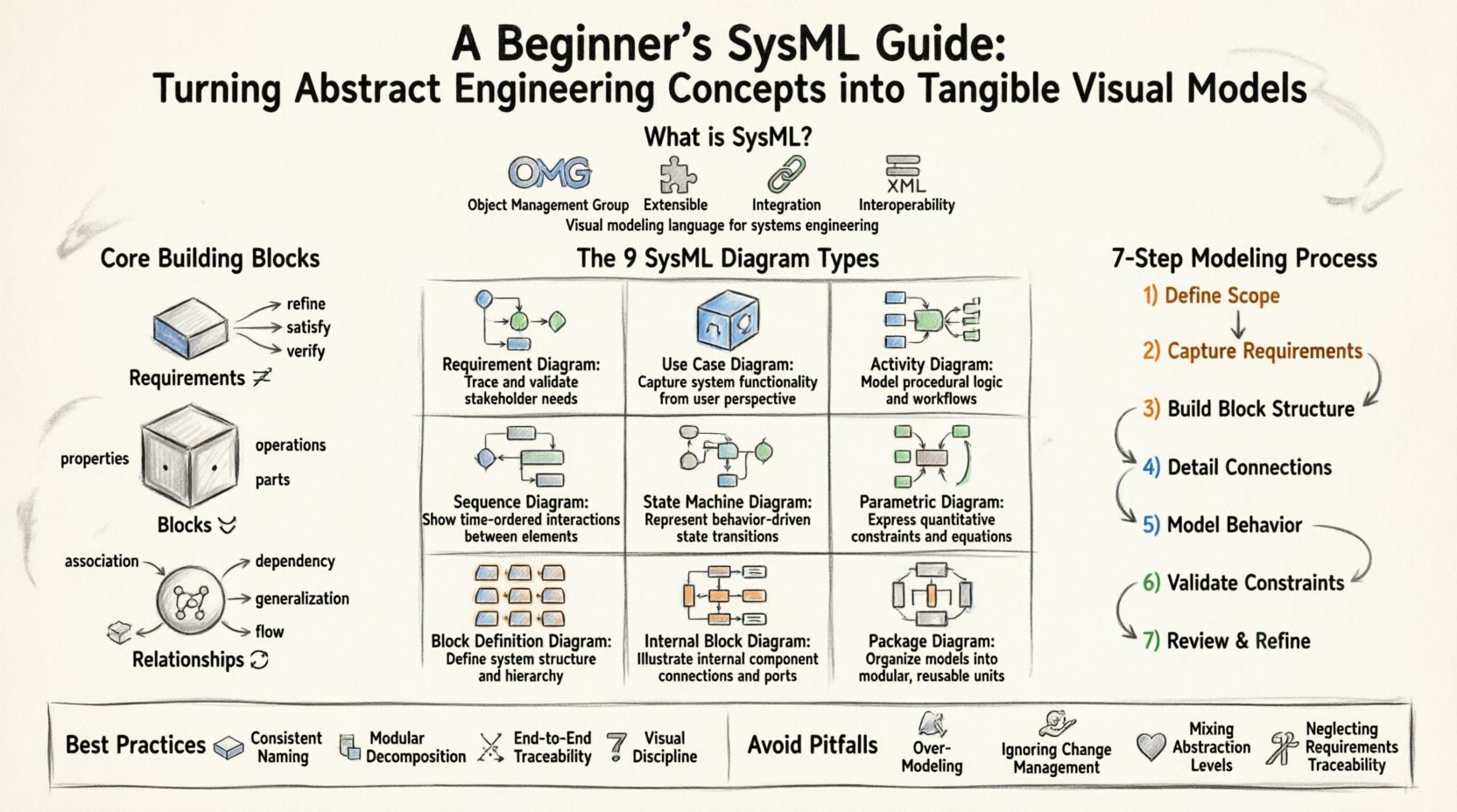
What is SysML? 📐
SysML is a general-purpose modeling language used for systems engineering applications. It is based on the Unified Modeling Language (UML) but extends it with specific capabilities required for systems engineering. While UML focuses primarily on software systems, SysML addresses physical, software, human, and process elements.
Key characteristics include:
- Standardization: Defined by the Object Management Group (OMG).
- Extensibility: Supports custom profiles and extensions.
- Integration: Links requirements directly to design and verification elements.
- Interoperability: Uses XML-based exchange formats (XMI) for data portability.
Using a modeling language allows teams to create a single source of truth. Instead of maintaining separate documents for requirements, design, and tests, SysML consolidates these views into a cohesive model. This reduces the risk of inconsistencies that often arise when multiple teams work from different specifications.
Why Visual Modeling Matters in Engineering 📊
Abstract concepts become tangible when visualized. Human brains process visual information significantly faster than text. Complex systems often involve interactions between mechanical, electrical, and software components. Describing these interactions solely in text can lead to misinterpretation.
Benefits of visual modeling include:
- Early Detection: Identify logical errors or missing interfaces before implementation begins.
- Communication: Provide a common language for stakeholders who may have different technical backgrounds.
- Traceability: Link high-level goals to specific design elements and test cases.
- Simulation: Enable analysis of system performance using parametric constraints.
Core Building Blocks 🧱
Before diving into diagrams, it is essential to understand the structural elements that make up a SysML model. These building blocks form the foundation upon which all diagrams are constructed.
1. Requirements 🔗
Requirements define what the system must do or be. In SysML, requirements are first-class citizens, not just text notes. They can be refined, satisfied, verified, and traced to other model elements.
- Internal Requirements: Constraints within a specific element.
- External Requirements: Needs defined outside the system boundary.
2. Blocks 📦
A block represents a physical or logical component within the system. It can be a subsystem, a device, or a software module. Blocks define the structure and behavior of the system.
- Properties: Attributes belonging to the block.
- Operations: Functions the block performs.
- Parts: Components contained within the block.
3. Relationships 🔄
Blocks interact through relationships. These define how data, energy, or control flows between components.
- Association: Structural link between blocks.
- Dependency: One element relies on another.
- Generalization: Inheritance relationships (specialization).
- Flow: Movement of items between ports.
The 9 SysML Diagram Types 🖼️
SysML organizes information into nine specific diagram types. Each serves a distinct purpose in capturing different aspects of the system. Understanding when to use which diagram is critical for effective modeling.
| Diagram Type | Focus Area | Primary Use Case |
|---|---|---|
| Requirement Diagram | Requirements | Manage system needs and traceability |
| Use Case Diagram | Functional Behavior | Identify actors and interactions |
| Activity Diagram | Workflow | Model logic and sequencing |
| Sequence Diagram | Interaction | Detail message passing over time |
| State Machine Diagram | State Changes | Define modes and transitions |
| Parametric Diagram | Constraints | Analyze performance and math |
| Block Definition Diagram (BDD) | Structure | Define system hierarchy |
| Internal Block Diagram (IBD) | Connection | Map internal connections and flows |
| Package Diagram | Organization | Group elements logically |
Deep Dive: Structural Diagrams
Structural diagrams describe the static aspects of the system. They are the skeleton of the model.
- Block Definition Diagram (BDD): Shows the hierarchy of blocks and their relationships. It answers the question: “What is made of what?”
- Internal Block Diagram (IBD): Shows the internal structure of a block. It details how parts connect via ports and connectors. It answers: “How do components talk to each other?”
Deep Dive: Behavioral Diagrams
Behavioral diagrams describe the dynamic aspects of the system. They answer: “What does the system do?”
- Use Case Diagram: Captures user goals and system responses. It is often the first step in understanding functional requirements.
- Activity Diagram: Similar to a flowchart, it models the flow of control and data between activities. It is useful for complex logic.
- State Machine Diagram: Describes the lifecycle of a block. It defines states (e.g., Idle, Running, Fault) and the events that trigger transitions.
- Sequence Diagram: Focuses on the interaction between objects over time. It is essential for understanding message passing protocols.
Deep Dive: Parametric and Requirement Diagrams
These diagrams bridge the gap between qualitative requirements and quantitative analysis.
- Requirement Diagram: Allows you to create requirement elements and link them to other model parts. You can specify satisfaction relationships, linking a requirement to a block that fulfills it.
- Parametric Diagram: Uses constraints to model mathematical relationships. For example, you can define a constraint where Power equals Voltage times Current. This allows for simulation and validation of physical properties.
Step-by-Step Modeling Process 🚀
Building a model is not a random activity. It follows a structured approach to ensure consistency and utility. The following workflow outlines a typical modeling lifecycle.
1. Define the Scope and Context
Start by identifying the system boundary. What is inside the system? What is outside? Define the external interfaces. This prevents scope creep and ensures the model remains focused.
2. Capture Requirements
Enter all known requirements into the Requirement Diagram. Categorize them (e.g., Functional, Performance, Interface). Ensure every requirement has a unique identifier.
3. Construct the Block Structure
Create the Block Definition Diagram. Break the system down into major subsystems. Define the ports and interfaces for each block. This establishes the architectural framework.
4. Detail Internal Connections
Open the Internal Block Diagram for key subsystems. Connect parts to ports. Define the types of data or energy flowing through these connections. This clarifies the physical or logical interdependencies.
5. Model Behavior
Use Use Case and Activity diagrams to describe how the system operates. If the system has distinct modes (e.g., Boot, Run, Shutdown), use State Machine diagrams. Ensure these behaviors align with the structural blocks defined earlier.
6. Validate with Constraints
Apply Parametric Diagrams to critical subsystems. Define equations that govern performance. Verify that the design meets the quantitative requirements identified in step 2.
7. Review and Refine
Conduct a model review with stakeholders. Check for completeness and consistency. Ensure all requirements are traced to design elements. Update the model as new information becomes available.
Best Practices for Clarity ✅
A model is only as good as its readability. If stakeholders cannot understand the model, the effort is wasted. Adhere to these guidelines to maintain high quality.
Consistent Naming Conventions
- Use clear, descriptive names for blocks and ports.
- Avoid abbreviations unless they are standard industry terms.
- Ensure naming matches the documentation used in requirements.
Modularization
- Use Packages to group related elements.
- Keep diagrams focused. A single diagram should not contain too many elements.
- Use reference blocks to reuse common structures across different subsystems.
Traceability Management
- Never leave a requirement unlinked.
- Ensure a clear path from high-level goals to low-level tests.
- Regularly check for broken links or orphaned elements.
Visual Discipline
- Arrange elements logically. Avoid crossing lines where possible.
- Use color coding sparingly to indicate status or type.
- Keep text concise within diagram shapes.
Common Pitfalls to Avoid ⚠️
New users often make specific mistakes that hinder the value of the model. Being aware of these traps helps maintain a healthy modeling environment.
1. Over-Modeling
Creating detailed models for every single component can lead to maintenance nightmares. Focus on the critical paths and interfaces. Not every detail requires a diagram.
2. Ignoring Change Management
Systems change frequently. A model that is not versioned or managed becomes obsolete quickly. Ensure there is a process for tracking changes and communicating updates to the team.
3. Mixing Levels of Abstraction
Do not mix high-level system views with low-level component details on the same diagram. This creates cognitive load and confusion. Separate strategic views from implementation details.
4. Neglecting Requirements
Designing without requirements leads to solutions that do not meet user needs. Always start with the “What” before defining the “How”.
Integration with Other Processes 🔄
SysML does not exist in a vacuum. It integrates with broader engineering processes.
- Agile Development: SysML can support agile by providing visual context for user stories and backlog items.
- Verification & Validation: Test cases can be linked directly to requirements and design blocks within the model.
- Simulation: Parametric models can be exported to simulation tools for performance analysis.
- Documentation: Reports can be generated from the model to ensure documentation stays synchronized with design.
Conclusion: Building a Strong Foundation 🏗️
Adopting Systems Modeling Language requires discipline and practice. It shifts the focus from documentation as a record to documentation as a design tool. By mastering the core blocks and diagrams, teams can reduce ambiguity and improve system quality.
Start small. Model a single subsystem first. Establish the links between requirements and design. As confidence grows, expand the scope. The goal is not to create a perfect model immediately, but to create a living artifact that supports decision-making throughout the project lifecycle.
Visual modeling turns abstract engineering concepts into tangible realities. It provides the structure needed to navigate complexity with confidence. With a solid understanding of SysML principles, engineers can build systems that are robust, verifiable, and aligned with stakeholder needs.