Model-Based Systems Engineering (MBSE) has transformed how complex systems are designed, analyzed, and validated. By shifting from document-centric processes to model-centric workflows, organizations gain a single source of truth for system architecture. However, the transition to the Systems Modeling Language (SysML) introduces specific technical challenges. Many engineering teams encounter validation failures that stall progress, obscure traceability, and compromise system integrity.
When a SysML model fails validation, it is not merely a syntax error; it is often a symptom of deeper conceptual misunderstandings regarding block definition, behavior flows, or requirement allocation. These errors propagate through the engineering lifecycle, leading to costly rework during integration or testing phases. This guide details the most frequent pitfalls encountered in SysML modeling and provides concrete corrective actions to restore model health and ensure validation compliance.
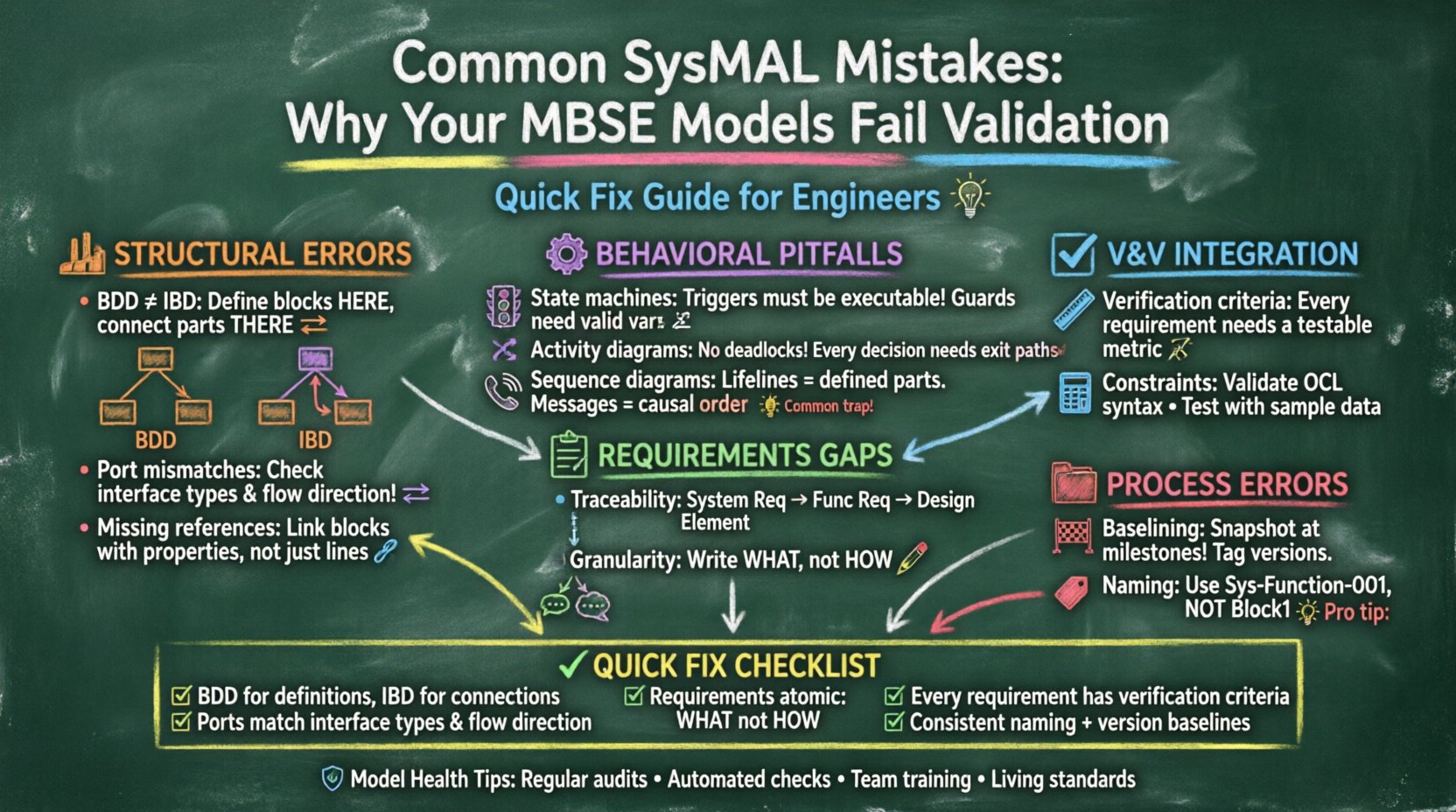
1. Structural Modeling Errors 🏗️
The foundation of any SysML model lies in its structural definitions. Errors here ripple outward, affecting behavior and requirements. A robust structure ensures that parts, ports, and connections are defined logically.
1.1 Confusing Block Definition Diagrams (BDD) and Internal Block Diagrams (IBD) 📐
One of the most pervasive mistakes is treating Blocks as interchangeable across different diagram types without regard for their specific roles. In a Block Definition Diagram (BDD), you define the abstraction of a system. In an Internal Block Diagram (IBD), you define the internal composition and connections of that system.
- Incorrect Approach: Defining ports, flows, and connectors directly on a BDD. BDDs should focus on class-like definitions and relationships between blocks, not internal connectivity.
- Impact: Validation tools flag these diagrams as structurally ambiguous. Traceability from requirements to internal implementation becomes broken.
- Correction: Use BDDs for defining the block hierarchy and properties. Use IBDs exclusively for defining parts, ports, and their internal connections. Ensure the Block in the IBD references the Block defined in the BDD.
1.2 Port Mismatches and Flow Issues 🔄
Ports are the interface points for data and energy exchange. Mismatches between interface definitions and actual usage are common sources of validation failure.
- Incorrect Approach: Connecting a standard port to a reference port without verifying the interface type. Ignoring the directionality of flow (send vs. receive).
- Impact: The model cannot simulate behavior accurately. Interfaces may appear connected, but the underlying types do not match, causing semantic errors.
- Correction: Ensure every connector links compatible port types. Use Interface Blocks to define standard behaviors for ports. Verify that the flow direction aligns with the interface definition (e.g., a signal flow vs. a part flow).
1.3 Missing or Ambiguous Reference Properties 📉
Reference properties define relationships between blocks (e.g., a Control Unit controls a Sensor). Omitting these or defining them incorrectly severs the logical link between components.
- Incorrect Approach: Relying solely on connectors in IBDs to represent ownership or control relationships without formal reference properties in the Block definition.
- Impact: Queries for system composition fail. You cannot easily generate a Bill of Materials (BOM) or determine system hierarchy programmatically.
- Correction: Define reference properties within the Block Definition. Use these properties in the IBD to instantiate the relationship. This separates the definition of the relationship from the specific instance of the connection.
2. Behavioral Modeling Pitfalls ⚙️
Behavioral diagrams describe how the system acts over time or under specific conditions. Errors here lead to models that cannot be simulated or verified against operational scenarios.
2.1 State Machine Transition Triggers 🚦
State machines are critical for defining state-dependent logic. A common error involves the definition of event triggers and guard conditions.
- Incorrect Approach: Using Boolean expressions that are not executable or referencing variables that do not exist in the state context.
- Impact: Simulation engines cannot evaluate transitions. The model hangs or behaves unpredictably during dynamic analysis.
- Correction: Ensure all trigger events are defined as signals or transitions. Guard conditions must reference valid parameters or properties available in the current context. Validate that every state has an exit path unless it is a final state.
2.2 Activity Diagram Flow Control 📊
Activity diagrams model the flow of control and data. Poor flow control leads to deadlocks or infinite loops in simulation.
- Incorrect Approach: Creating circular dependencies without exit conditions. Failing to define input and output pins correctly on nodes.
- Impact: Validation tools report unreachable nodes or cycles that prevent termination.
- Correction: Map data flows explicitly. Ensure every decision node has a true/false path that converges eventually. Use merge nodes correctly to combine flows without losing data context.
2.3 Interaction and Sequence Misalignment 📞
Sequence diagrams show object interactions over time. Errors here often stem from mismatched lifelines or message ordering.
- Incorrect Approach: Sending messages to objects that do not exist in the current scope or ignoring the order of execution.
- Impact: Interface validation fails. The sequence of operations does not reflect the physical reality of the system.
- Correction: Align lifelines with defined Parts. Ensure message ordering reflects causality. Use combined fragments (alt, opt, loop) to handle conditional logic correctly.
3. Requirements and Traceability Gaps 📋
The core value of MBSE is traceability. If requirements are not linked to design elements, the model loses its verification purpose.
3.1 Broken Requirement Traceability Links 🔗
Requirements must be allocated to specific system elements. Gaps in this allocation make verification impossible.
- Incorrect Approach: Linking requirements only to other requirements, or leaving them orphaned without a parent or child link.
- Impact: Verification matrices cannot be generated. Stakeholders cannot see how a requirement is satisfied.
- Correction: Establish a clear hierarchy: System Requirement -> Functional Requirement -> Design Element. Use the Requirement diagram to visualize these links. Ensure every requirement has at least one allocation path.
3.2 Mixed Granularity in Requirements 🧩
Requirements should be atomic. Mixing high-level goals with low-level implementation details in a single requirement creates confusion.
- Incorrect Approach: Writing requirements that contain both a “what” and a “how” (e.g., “The system shall use a 5V power supply to turn on the light”).
- Impact: Validation fails because the design changes, but the requirement remains. It becomes impossible to determine if the requirement is satisfied.
- Correction: Write requirements based on the “what” (functionality). Move the “how” (implementation) to design constraints or specifications. This allows the design to evolve without rewriting requirements.
4. Verification and Validation (V&V) Integration Issues ✅
Validation ensures the right system is built; verification ensures the system is built right. SysML supports this through verification criteria.
4.1 Missing Verification Criteria 📝
Every requirement that needs verification must have a corresponding verification method defined in the model.
- Incorrect Approach: Defining a requirement but leaving the verification field empty or generic.
- Impact: The model cannot be validated against the requirement. Test cases cannot be generated automatically.
- Correction: Define specific verification criteria for each requirement. Link these criteria to test cases or simulation scenarios. Ensure the criterion is measurable and testable.
4.2 Constraint Satisfaction Failures 🧮
OCL (Object Constraint Language) or other constraint mechanisms are used to enforce rules. Incorrect syntax or logic breaks validation.
- Incorrect Approach: Using constraints that reference non-existent properties or logical operators that create contradictions.
- Impact: The model becomes unsatisfiable. No valid solution exists for the defined constraints.
- Correction: Validate constraint syntax before applying. Test constraints with sample data. Ensure constraints are consistent with the rest of the model logic.
5. Process and Versioning Errors 📂
Even a perfect model can fail validation if the process surrounding it is flawed. Version control and baselining are critical.
5.1 Lack of Baselining 🏁
Without baselines, you cannot track changes or revert to known good states.
- Incorrect Approach: Making continuous changes without saving snapshots of the model state.
- Impact: Regression issues are hard to isolate. Validation results fluctuate without clear reason.
- Correction: Establish baselines at key milestones. Tag model versions in the repository. Document what changed between baselines.
5.2 Inconsistent Naming Conventions 🏷️
Names should be unique and descriptive. Ambiguity leads to confusion and validation errors.
- Incorrect Approach: Using generic names like “Block1”, “PortA”, or “Requirement1”.
- Impact: Automated tools cannot generate reports. Humans cannot understand the model without context.
- Correction: Adopt a naming standard (e.g., “Sys-Function-001”, “Part-Hydraulic-01”). Enforce this standard through model templates or check scripts.
Common Errors vs. Corrective Actions Table 📊
The following table summarizes the critical mistakes and their solutions for quick reference.
| Category | Common Mistake | Impact on Validation | Corrective Action |
|---|---|---|---|
| Structure | Defining ports on BDD instead of IBD | Semantic ambiguity, broken connectivity | Move port definitions to Internal Block Diagrams |
| Behavior | Circular transitions in State Machines | Infinite loop in simulation, deadlock | Ensure exit paths and valid guard conditions |
| Requirements | Orphaned requirements | Traceability gap, unverifiable specs | Link requirements to Blocks and Activities |
| Verification | Missing verification criteria | Cannot generate test cases | Add verification criteria to every requirement |
| Process | Generic naming conventions | Confusion, poor reporting | Implement strict naming standards |
Deep Dive: Constraint Logic and Data Types 🧠
One nuanced area where models often fail is the handling of data types within constraints. SysML supports basic types, but complex systems often require custom types.
6.1 Unit Inconsistency ⚖️
Physics-based systems rely on units (e.g., meters, seconds, volts). Mixing units without conversion causes validation failures.
- Issue: Defining a property as “Length” without specifying units, then comparing it to a value with units.
- Resolution: Use unit-aware properties where the tooling supports it. Ensure all arithmetic operations respect unit conversion rules.
6.2 Parameter Propagation 📈
Parameters define the values of properties. If parameters are not propagated correctly through the hierarchy, values are lost.
- Issue: Defining a parameter at the top level but failing to allocate it to child blocks that need it.
- Resolution: Use the allocation relationship to pass parameters down the hierarchy. Verify that child blocks inherit the parameter constraints.
Ensuring Long-Term Model Health 🛡️
Correcting validation errors is not a one-time task. Maintaining a healthy model requires discipline.
- Regular Audits: Schedule periodic reviews of model structure and behavior. Check for unused blocks or orphaned requirements.
- Automated Checks: If your modeling environment supports it, use scripts to run validation checks automatically upon save.
- Training: Ensure all modelers understand the difference between BDD and IBD, and the rules of requirement allocation.
- Documentation: Maintain a modeling standard document. Reference it when onboarding new team members.
By addressing these specific areas, you move from a fragile model that breaks under scrutiny to a robust asset that drives engineering confidence. Validation is not a gate to pass; it is a continuous feedback loop that ensures the model remains an accurate representation of the system.
Focus on the structure, enforce the behavior, link the requirements, and verify the constraints. This disciplined approach reduces technical debt and ensures your MBSE implementation delivers value from concept through retirement.