Model-Based Systems Engineering (MBSE) transforms how complex systems are defined, designed, and verified. It shifts the focus from document-centric processes to model-centric workflows. Systems Modeling Language (SysML) serves as the foundation for this shift, providing a standardized way to represent system structure, behavior, and requirements. However, the transition from a conceptual diagram to a functional model often exposes gaps that static documentation hides.
This guide explores a practical case study involving an elevator system. While the concept appears straightforward, the modeling process in SysML uncovers intricate behavioral issues, timing constraints, and interface ambiguities. By dissecting this example, we examine how rigorous modeling practices reveal hidden complexities that are critical for safety and reliability.
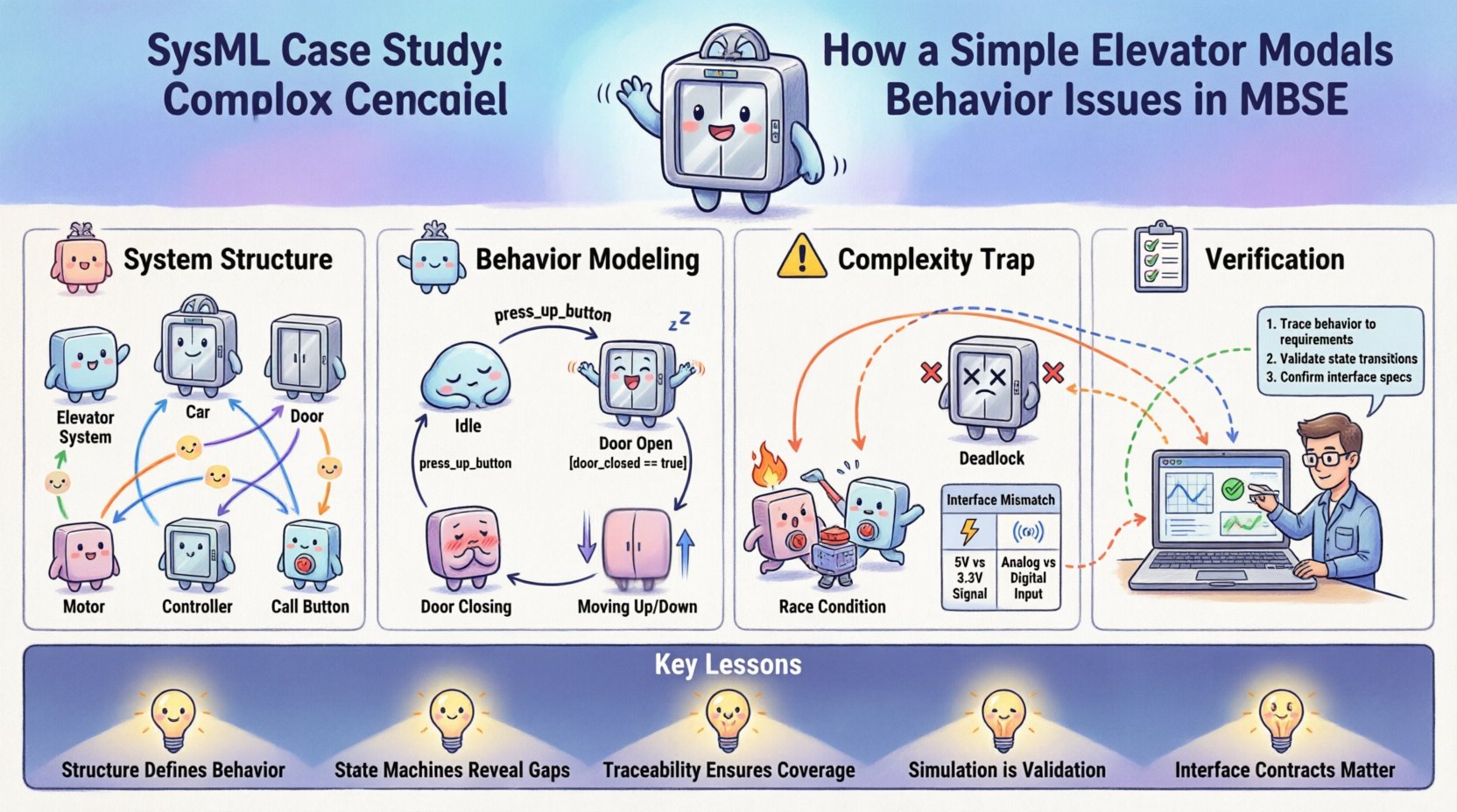
🏗️ Understanding the System Structure
The first step in SysML modeling is defining the system boundaries and composition. For an elevator, the structure is not merely a car moving up and down. It involves multiple subsystems interacting through defined interfaces.
1.1 Block Definition Diagram (BDD) 🧩
A Block Definition Diagram establishes the types of objects within the system. In this scenario, we define the following primary blocks:
- Elevator System: The top-level container.
- Car: The passenger compartment.
- Door: The access mechanism.
- Motor: The propulsion unit.
- Controller: The logic unit managing operations.
- Call Button: The user interface for input.
These blocks are related through generalization and composition relationships. For instance, the Elevator System is composed of a Car, a Door, and a Motor. This structural definition ensures that every physical component has a corresponding model element.
1.2 Internal Block Diagram (IBD) 🔄
While the BDD defines types, the Internal Block Diagram defines instances and connections. This is where the flow of data and energy is specified.
- Ports: Define interaction points. For example, the Motor requires a Power Port, while the Controller requires a Signal Port.
- Flow Properties: Define what moves between ports. Electrical signals flow from the Call Button to the Controller. Mechanical power flows from the Motor to the Car.
- References: Link parts to their respective blocks.
Creating a detailed IBD forces the engineer to specify exactly how the Controller communicates with the Door. Is it a direct physical link, or a logical signal? This distinction often gets lost in text-based requirements but becomes explicit in the model.
🧠 Modeling Behavior with State Machines
Structure alone does not define functionality. SysML uses State Machine Diagrams to model the dynamic behavior of the system. This is where the elevator case study begins to reveal significant complexity.
2.1 Defining States ⏸️
A State Machine represents the lifecycle of a specific block or the system as a whole. Common states for an elevator include:
- Idle: Waiting for a call.
- Door Open: Accessible to passengers.
- Door Closing: Transitioning to a closed state.
- Moving Up: Ascending to a floor.
- Moving Down: Descending to a floor.
- Stopped: Arrived at a floor, doors closed.
Each state represents a stable condition where the system performs specific activities or waits for an event.
2.2 Transitions and Events ⚡
Transitions occur when an event is triggered. Events can be external (a button press) or internal (a sensor signal). Guards determine if a transition is allowed.
Consider the transition from Door Open to Door Closing:
- Event: Timer expires or Door Closed Signal.
- Guard: No obstruction detected in the doorway.
- Action: Activate Door Motor.
Here, the model reveals a potential issue. If the guard condition relies solely on a timer, the system might close the door on a passenger. If it relies solely on an obstruction sensor, the door might never close if the sensor is faulty. The model forces the engineer to define the priority logic between these conflicting inputs.
🕸️ The Complexity Trap: Timing and Interactions
The most significant value of this case study lies in the discovery of timing issues. A simple state machine often assumes instantaneous transitions, but real-world systems operate in continuous time.
3.1 Race Conditions ⏱️
A race condition occurs when the system’s behavior depends on the sequence or timing of events. In the elevator model, consider the scenario where a passenger presses a floor button while the door is closing.
Scenario A: The button press is processed before the door closes completely. The system opens the door and moves to the requested floor.
Scenario B: The door closes completely before the button press is registered. The system moves to the requested floor only after the current trip is complete.
Without simulation or precise timing constraints in the model, these two outcomes are indistinguishable. SysML Activity Diagrams can help visualize the sequence of actions, but State Machines must be annotated with timing constraints to prevent ambiguity.
3.2 Deadlock Scenarios 🚫
A deadlock happens when the system enters a state where no further transitions are possible. This is a critical failure mode.
In the elevator model, a deadlock could occur if:
- The Car is between floors.
- The Door is locked.
- The Motor is powered off.
- No emergency call has been registered.
If the power fails in this state, the system cannot move. The model must include an Emergency Power State or a Rescue Mode that overrides standard logic. Identifying this requirement early in the modeling phase prevents costly hardware changes later.
3.3 Interface Mismatches 📡
Complex behavior often arises from mismatches between subsystems. The Controller sends a signal to the Motor. The Motor expects a specific voltage range. The Model must define the interface contract.
| Interface Element | Expected Value | Real-World Variance | Risk |
|---|---|---|---|
| Signal Latency | < 50ms | Variable due to wiring | Door safety delay |
| Power Voltage | 24V DC | 20V – 28V | Motor stall |
| Door Sensor | Binary (On/Off) | Analog noise | Fake open signal |
By mapping these interfaces in the IBD, the engineer can see where signal degradation might occur. This visibility is impossible with a flat requirements document.
🔍 Verification and Traceability
One of the core promises of MBSE is traceability. Every element in the model should link back to a requirement and forward to a test case. The elevator model demonstrates the power of this linkage.
4.1 Requirement Allocation 📋
Requirements are not just text; they are constraints on the model. For example:
- REQ-01: The elevator must respond to a call within 3 seconds.
- REQ-02: The door must not close if an obstruction is detected.
In the model, REQ-01 constrains the State Machine transition time. REQ-02 constrains the Guard condition on the Door Closing transition. If the model cannot satisfy a constraint, the requirement is flagged as unverified.
4.2 Simulation and Validation 🎮
Static models are static. To verify behavior, the model must be simulated. Simulation allows the engineer to inject events and observe the system response.
Simulation Steps:
- Initialize the system in the Idle state.
- Trigger a Call Request event at Floor 3.
- Observe the transition to Moving Up.
- Inject an Obstruction event during Door Closing.
- Verify the system reverts to Door Open.
If the simulation fails at step 5, the model logic is incorrect. This feedback loop allows for iterative refinement before any physical hardware is built.
🛠️ Common Modeling Pitfalls
Even with a clear case study, engineers often introduce errors into the SysML model. Recognizing these pitfalls is essential for maintaining model integrity.
5.1 Over-Abstraction 🌫️
Creating a model that is too abstract hides critical details. If the Motor block is treated as a black box with no internal behavior, the engineer cannot verify its response time. The model must be detailed enough to support the required level of analysis.
5.2 Under-Abstraction 🧱
Conversely, modeling every screw and bolt is inefficient. The model should focus on the system level behavior relevant to the current phase of development. Granularity must match the project stage.
5.3 Inconsistent Notation 📝
Using different conventions for naming states or blocks creates confusion. A standardized naming convention is vital. For example, always naming states in the Present Tense (e.g., Door Closed instead of Door Closing for the state itself).
📈 Lessons Learned from the Elevator Model
This case study highlights several key takeaways for systems engineering.
- Structure Defines Behavior: You cannot model behavior without a defined structure. The IBD dictates the available interactions.
- State Machines Reveal Logic Gaps: Explicitly defining states forces the engineer to consider edge cases like power loss or sensor failure.
- Traceability Ensures Coverage: Linking requirements to model elements ensures no safety constraint is overlooked.
- Simulation is Validation: Running the model is the only way to verify timing and interaction logic.
- Interface Contracts Matter: Defining ports and flows prevents integration issues between subsystems.
🚀 Moving Forward in MBSE
The elevator example is a microcosm of larger systems. Whether designing a spacecraft, an automotive braking system, or a medical device, the principles remain the same. Complexity is not eliminated by abstraction; it is managed through rigorous modeling.
As projects grow in scale, the discipline of SysML becomes even more critical. It provides a single source of truth that aligns engineering, software, and hardware teams. By treating the model as a living artifact rather than a static diagram, organizations can reduce risk and improve product quality.
The journey from a simple diagram to a verified simulation requires patience and precision. But the insights gained regarding behavior, timing, and interaction are invaluable. They transform the engineering process from a guess-and-check exercise into a predictable, verifiable workflow.
Ultimately, the goal is not just to build a system that works, but to build a system that is understood. The model is the understanding. The simulation is the proof. And the requirements are the promise.