Introduction to the Integration Challenge 💡
Systems engineering is inherently complex. When moving from conceptual models to physical hardware, the margin for error shrinks significantly. One of the most critical areas where projects often stumble is requirement traceability. This case study examines a real-world scenario where a hardware integration effort failed, not because of a lack of technical skill, but due to a breakdown in how requirements were linked to system behavior within a Systems Modeling Language (SysML) framework. The goal is to dissect the failure points, understand the technical implications, and outline how rigorous modeling can prevent similar outcomes.
Traceability is more than just a checklist item. It is the backbone of system integrity. When a requirement is not linked to a design element, there is no way to verify if that element actually satisfies the intent. In high-stakes environments, such as aerospace or autonomous vehicle development, this disconnect can lead to costly rework, schedule delays, and safety risks. This analysis focuses on the mechanics of the failure and the specific SysML constructs that were underutilized or misapplied.
Project Background and Scope 📦
The project in question involved the development of a multi-sensor fusion unit for an autonomous navigation platform. The system required the integration of LIDAR, radar, and optical cameras into a unified processing node. The development lifecycle followed a Model-Based Systems Engineering (MBSE) approach, utilizing SysML to define the architecture and requirements.
Key Project Parameters:
- System Type: Autonomous Navigation Sensor Suite
- Development Phase: System Integration and Verification
- Primary Technology: SysML for modeling and specification
- Outcome: Integration failure due to unverified requirement gaps
The team created a comprehensive set of requirements during the early phases. However, the linkage between these textual requirements and the physical design blocks was inconsistent. While the initial system architecture was modeled, the detailed integration phase lacked the necessary rigor in the traceability chains. This disconnect became apparent only when the first physical prototypes were assembled.
The Role of SysML in Modern Systems Engineering 🧩
SysML provides a standardized way to describe system structures, behaviors, and requirements. In a well-structured model, every requirement should be decomposed, allocated, and verified. The language supports several diagram types, including:
- Requirement Diagrams: Define the “what” of the system.
- Block Definition Diagrams (BDD): Define the “structure” of the system.
- Internal Block Diagrams (IBD): Define the “interfaces” and connections between blocks.
- Parametric Diagrams: Define the “constraints” and mathematical relationships.
In the scenario being analyzed, the Requirement Diagrams were populated extensively. The team successfully captured functional and non-functional requirements. However, the allocation of these requirements to specific blocks in the BDD and IBD was loose. Many requirements were left orphaned, meaning they existed in the model but had no outgoing relationships to design elements. This created a false sense of completeness. The model looked populated, but the logical flow of validation was broken.
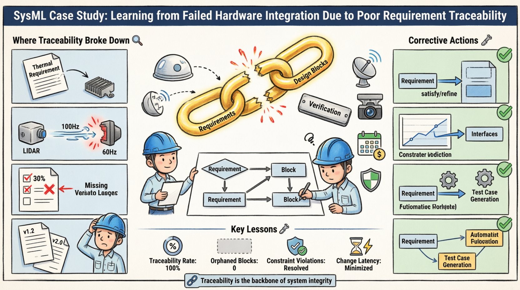
Where Traceability Broke Down 🔍
The failure was not a single event but a series of small oversights that compounded over time. The following points detail where the traceability chains fractured during the modeling process.
1. Inconsistent Requirement Allocation
During the requirement analysis phase, engineers allocated requirements to high-level system blocks. As the design moved to subsystems, these allocations were not propagated down. For example, a thermal management requirement was assigned to the “Sensor Unit” block but was never linked to the specific “Heat Sink” component in the internal block diagram. When the hardware was fabricated, the heat sink was undersized because the thermal requirement was not actively driving the design constraints.
2. Interface Definition Gaps
Internal Block Diagrams define the ports and connectors between components. In this case, the data flow interfaces were modeled, but the signal timing requirements were not linked to the interface ports. The LIDAR data stream was expected to run at 100Hz, but the requirement specifying this frequency was not attached to the communication interface port. Consequently, the interface controller was designed for 60Hz, causing data loss during integration.
3. Verification Links Missing
A robust model requires a verification link. This connects a requirement to a test case or a specific design element that proves the requirement is met. The project team neglected to create these verification links for approximately 30% of the requirements. Without these links, there was no automated way to generate a verification plan. The testing phase became manual and ad-hoc, leading to missed coverage areas.
4. Version Control and Baseline Drift
Requirements evolved throughout the project. Change requests were made to accommodate new sensor technologies. However, the model did not enforce strict versioning on the requirement-block relationships. When a requirement changed, the upstream design blocks were not flagged for review. This drift meant the hardware was built to an older version of the specification, which was no longer current in the system model.
Comparison of Modeling States 📊
To visualize the gap between the intended state and the actual state of the model, consider the following comparison table. This highlights the specific areas where traceability was insufficient.
| Traceability Aspect | Intended State (Ideal) | Actual State (Observed) | Resulting Issue |
|---|---|---|---|
| Requirement Allocation | 100% of requirements linked to design blocks | 70% of requirements linked to design blocks | Unverified design decisions |
| Interface Constraints | Signal timing linked to port properties | Timing constraints in text only | Interface mismatch (60Hz vs 100Hz) |
| Verification Links | Direct link to test cases | Manual traceability matrix | Missed test coverage |
| Change Management | Automatic impact analysis on change | Manual review required | Outdated hardware builds |
Detailed Impact Analysis 📉
The consequences of poor traceability were immediate and measurable. The integration phase, which was scheduled to take four weeks, extended to twelve weeks. The root cause analysis revealed that the hardware had to be redesigned to meet the original requirements that were forgotten during the modeling phase.
Cost Implications
Redesigning the sensor housing and the communication interface board incurred significant material and labor costs. The procurement of new components led to price increases due to expedited shipping. The budget overage was directly attributable to the rework required to fix the unlinked requirements.
Schedule Delays
Integration testing could not proceed until the hardware matched the specification. The delay pushed back the software integration phase. Since the software depended on the hardware signals, the entire system validation timeline was compressed. This forced the team to work overtime to meet the launch deadline, increasing the risk of introducing new errors.
Safety Risks
The most critical impact involved safety. The thermal management failure meant that the sensors could overheat in high-ambient temperature conditions. This was not caught during initial testing because the thermal requirement was not actively monitored in the model. In a production environment, this could have led to system failure during operation, posing a risk to personnel and property.
Corrective Actions and SysML Improvements 🛠️
Once the failure was identified, the engineering team implemented a corrective strategy focused on strengthening the traceability chains within the SysML model. The following steps were taken to restore integrity to the system definition.
1. Enforced Allocation Rules
The team established a rule that no requirement could be moved to the next development phase without a valid allocation to a design block. This was enforced through model validation scripts. If a requirement had no outgoing “satisfy” or “refine” relationship, the model would flag it as incomplete. This forced engineers to link every requirement to a physical or logical component.
2. Interface Constraint Integration
Signal timing and data rate requirements were moved from text documents into the parametric diagrams. These diagrams now explicitly constrain the properties of the interface ports. This ensures that if a requirement changes, the interface constraints update automatically, triggering a notification to the design team.
3. Automated Verification Planning
The team implemented a workflow where verification links generate test cases automatically. Every requirement with a verification link creates a pending test item in the quality management system. This ensures that no requirement is verified without a corresponding test plan. This reduces the risk of manual error in tracking test coverage.
4. Change Impact Analysis
When a requirement was modified, the model was queried to find all downstream dependencies. Any block that satisfied or refined that requirement was highlighted. This visual feedback allowed the team to see exactly which hardware components needed to be re-evaluated before implementing the change.
Lessons for Future Projects 🚀
This case study offers several takeaways for systems engineering teams adopting MBSE. The primary lesson is that the model is only as good as the links within it. A model full of disconnected elements provides no value during integration.
- Traceability is a Continuous Process: It is not a task to be completed at the end of a phase. Traceability must be maintained throughout the lifecycle as requirements evolve.
- Links Drive Design: Requirements should drive the creation of design elements, not the other way around. If a design element exists without a requirement, it is technically technical debt.
- Validation is Key: Verification links must be established early. Waiting until the hardware is built to verify requirements is too late.
- Tooling Support: While software tools were not mentioned specifically, the capability to query relationships and visualize dependencies is essential. Manual tracking is prone to error.
Implementing Robust Traceability Chains 🔗
To prevent recurrence, the following checklist should be applied to all SysML models before moving to hardware fabrication.
Pre-Integration Checklist
- Requirement Coverage: Are all requirements allocated to at least one block?
- Interface Completeness: Do all physical interfaces have defined data types and timing constraints?
- Constraint Validation: Are parametric constraints satisfied by the current design values?
- Verification Links: Does every requirement have a path to a test case or validation method?
- Change History: Is the version of the model synchronized with the version of the hardware specifications?
Monitoring Metrics
Teams should track specific metrics to ensure traceability health. These metrics can be extracted from the model repository.
- Traceability Rate: Percentage of requirements with valid links.
- Orphaned Blocks: Number of design blocks with no associated requirements.
- Constraint Violations: Number of parametric constraints that are currently violated.
- Change Latency: Time elapsed between a requirement change and the model update.
Final Thoughts on Model-Based Systems Engineering 🏁
The failure described in this case study serves as a stark reminder of the importance of discipline in systems engineering. SysML is a powerful tool that enables clarity and rigor, but it requires active management. The technology does not automatically enforce good practices; the engineers must define and enforce them.
By treating the model as the single source of truth and ensuring that every line of code and every component on a circuit board can be traced back to a specific requirement, organizations can mitigate the risks of integration failure. The path to successful hardware integration is paved with clear, unbroken chains of traceability. When these chains are broken, the physical system suffers. When they are strong, the system is robust, reliable, and aligned with its original intent.
Future projects should invest in training and process definition around traceability. This includes defining what constitutes a valid link and establishing governance around model changes. The cost of prevention is always lower than the cost of correction. In the context of complex hardware integration, the difference between success and failure often lies in the details of how requirements are connected within the model.