Model-Based Systems Engineering (MBSE) relies on the precision and integrity of the system model. A SysML model serves as the single source of truth for design, analysis, and verification. However, the complexity inherent in modern systems increases the risk of errors within the model itself. Without a rigorous validation process, inconsistencies can propagate, leading to costly rework or system failures during implementation. This guide outlines the essential validation steps required to ensure your SysML model is robust, consistent, and ready for final submission.
Before handing over a model to stakeholders, developers, or verification teams, a practitioner must verify structural integrity, traceability, behavioral logic, and parametric constraints. The following sections detail the specific checks required to maintain model quality.
Why Validation Matters in MBSE 📉
An unchecked model is a liability. In systems engineering, the cost of fixing a requirement error in the design phase is exponentially lower than fixing it during testing or deployment. However, model errors often remain invisible until a specific analysis is run or a stakeholder reviews a generated report.
Validation ensures that the model accurately represents the system requirements and that the logical relationships between system elements are sound. It prevents scenarios where:
- Requirements exist without corresponding design elements.
- Behavioral states are unreachable or dead-locked.
- Parametric equations result in undefined values or unit mismatches.
- Traceability links are broken or circular.
Running a structured checklist mitigates these risks and establishes confidence in the engineering artifacts.
Structural Integrity and Block Definition ✅
The foundation of any SysML model lies in its Block Definition Diagram (BDD). This structure defines the physical and logical composition of the system. Before submission, the structural model must undergo a thorough audit.
1. Block Definition Consistency
Ensure that every block defined in the model is unique and distinct. Avoid duplication of block definitions across different packages unless intentional for context-specific variations.
- Uniqueness: Check for blocks with identical names in different namespaces. This can confuse downstream tools and stakeholders.
- Properties: Verify that all parts and ports are correctly typed. A part must reference a valid block definition.
- Relationships: Ensure that associations, aggregations, and compositions are defined correctly. Misusing a composition relationship for a loose association can lead to incorrect ownership semantics.
2. Package Organization
A well-organized package structure is vital for navigation and maintenance. Before finalizing, review the package hierarchy.
- Naming Conventions: Ensure all packages follow the established organizational naming standard.
- Visibility: Check package visibility settings. Ensure that elements within private packages are not inadvertently exposed to external contexts unless intended.
- Imports: Review import statements. Ensure that external dependencies are necessary and do not create circular dependencies between packages.
Requirements Traceability and Allocation 📋
Traceability is the backbone of systems engineering. It links the “what” (requirements) to the “how” (design). A model without complete traceability is incomplete.
1. Requirement Linking
Verify that every requirement element has at least one outgoing link to a design element (Block, Use Case, or Activity).
- Satisfied Links: Confirm that design elements satisfy the requirements assigned to them.
- Verified Links: Ensure that verification methods are linked to requirements to define how compliance is measured.
- Refined Links: Check for parent-child relationships between high-level and detailed requirements. Ensure no orphaned sub-requirements exist.
2. Allocation Matrix
Use a requirements allocation matrix or view to visualize the mapping. This helps identify gaps where a requirement has no design counterpart.
| Validation Step | Criteria | Outcome |
|---|---|---|
| Requirement Coverage | 100% of requirements have a target | Design completeness |
| Duplicate Allocation | No requirement allocated to multiple blocks without justification | Clear ownership |
| Traceability Depth | Links extend to lowest level of design | Implementation readiness |
3. Use Case and Activity Coverage
Functional requirements must map to use cases or activities. Verify that:
- Every use case has a defined trigger.
- Activities contain enough detail to be executable or analyzable.
- Flow connections between activities are logical and do not create loops unless explicitly intended.
Behavioral Consistency and State Machines ⚙️
Behavior diagrams, such as State Machine Diagrams (SMD) and Sequence Diagrams, define how the system reacts to events. These are common sources of logical errors.
1. State Machine Validation
State machines must be free of deadlocks and unreachable states.
- Initial/Final States: Ensure every state machine has exactly one initial pseudo-state and one or more final states.
- Transitions: Check that every state has at least one outgoing transition. Isolated states indicate incomplete logic.
- Guards: Verify that transition guards cover all possible conditions. If a state has multiple outgoing transitions, the guards should be mutually exclusive or prioritize correctly.
- History States: If history states are used, ensure they reference valid parent states and do not create circular references.
2. Sequence and Communication
Sequence diagrams illustrate the flow of messages over time. Validate these by checking:
- Message Lifelines: Ensure all messages originate from a valid lifeline and target a valid object or actor.
- Ordering: Verify that the sequence of events aligns with the system’s operational logic.
- Self-Interaction: Check for self-messages that are necessary for internal processing.
Parametric Constraint Verification 📊
Parametric diagrams link physical properties to mathematical constraints. Errors here can lead to unrealistic performance predictions.
1. Constraint Block Integrity
Constraint blocks define the equations used for analysis. Validate them by ensuring:
- Unit Consistency: All variables within an equation must share compatible units. Mismatches lead to calculation errors.
- Solvability: Ensure the number of unknowns matches the number of constraints. Over-constrained systems may have no solution; under-constrained systems may have infinite solutions.
- Variable Binding: Verify that every variable in a constraint block is bound to a real property (e.g., mass, velocity, force) within the system model.
2. Analysis Flow
Check that the parametric model allows for the intended analysis type.
- Inputs vs. Outputs: Clearly distinguish between design parameters (inputs) and performance metrics (outputs).
- Constraints: Ensure that boundary constraints (e.g., maximum temperature) are correctly defined to limit the solution space.
Documentation and Metadata Standards 📝
A model is not just about diagrams; it is about information. Metadata ensures that the model remains understandable over time.
1. Element Documentation
Every significant element should have a description. Check for:
- Comments: Ensure comments are present for complex blocks, ports, and relationships.
- Notes: Use notes to store external information, such as references to external standards or regulatory requirements.
- Tags: Utilize tagged values for specific properties (e.g., version, owner, cost) that are not part of the standard SysML schema.
2. Stereotypes and Profiles
If the project uses custom profiles, verify that they are correctly applied.
- Consistency: Ensure that stereotypes are applied consistently across the model.
- Validity: Check that stereotype properties match the definition in the profile package.
Common Pitfalls to Avoid ⚠️
Even experienced practitioners encounter recurring issues. Awareness of these common pitfalls can save significant time during the review phase.
- Orphaned Elements: Elements that exist in the model but are not connected to any diagram or requirement. These clutter the model and confuse reviewers.
- Version Drift: Ensure the model version matches the documentation version. Discrepancies here undermine trust.
- Circular Dependencies: Avoid circular references between packages or constraints, which can cause solver failures.
- Redundant Diagrams: Do not create multiple diagrams showing the same information in different ways. Consolidate views to reduce maintenance overhead.
- Hardcoded Values: Avoid embedding specific values in equations that should be variables. This reduces flexibility for future scenarios.
Final Review Workflow 🔄
Once the technical checks are complete, a procedural review ensures the submission meets organizational standards.
1. Peer Review
Assign the model to a peer for independent verification. A second set of eyes often catches errors the primary author overlooks.
- Focus on high-risk areas, such as safety-critical constraints or complex state logic.
- Verify that feedback from previous reviews has been addressed.
2. Automated Validation
Utilize built-in validation features of the modeling environment. Run syntax checks and consistency reports.
- Resolve all critical errors flagged by the engine.
- Review warnings to determine if they require remediation or justification.
3. Export and Verification
Generate reports or exports to verify the data integrity outside the modeling environment.
- Check requirement reports to ensure links are intact.
- Review exported diagrams to ensure they render correctly.
- Validate that metadata is preserved during export.
Summary of Critical Validation Points 📌
| Domain | Key Check | Impact of Failure |
|---|---|---|
| Structure | Block relationships and types | Incorrect system composition |
| Requirements | Traceability links | Unverified requirements |
| Behavior | State transitions and guards | Logic deadlocks or errors |
| Parametric | Unit consistency and solvability | Invalid simulation results |
| Metadata | Comments and tags | Loss of context and history |
Implementation and Maintenance 🏗️
Validation is not a one-time event. As the system evolves, the model must evolve with it. Integrating these validation steps into the regular development cycle ensures long-term model health.
- Incremental Checks: Run structural and traceability checks after every major change.
- Periodic Audits: Schedule a full model audit at major milestones.
- Continuous Improvement: Update the checklist based on lessons learned from previous projects.
By adhering to this comprehensive checklist, practitioners ensure that their SysML models are not just diagrams, but reliable engineering assets. This discipline reduces risk, improves communication, and supports the successful delivery of complex systems.
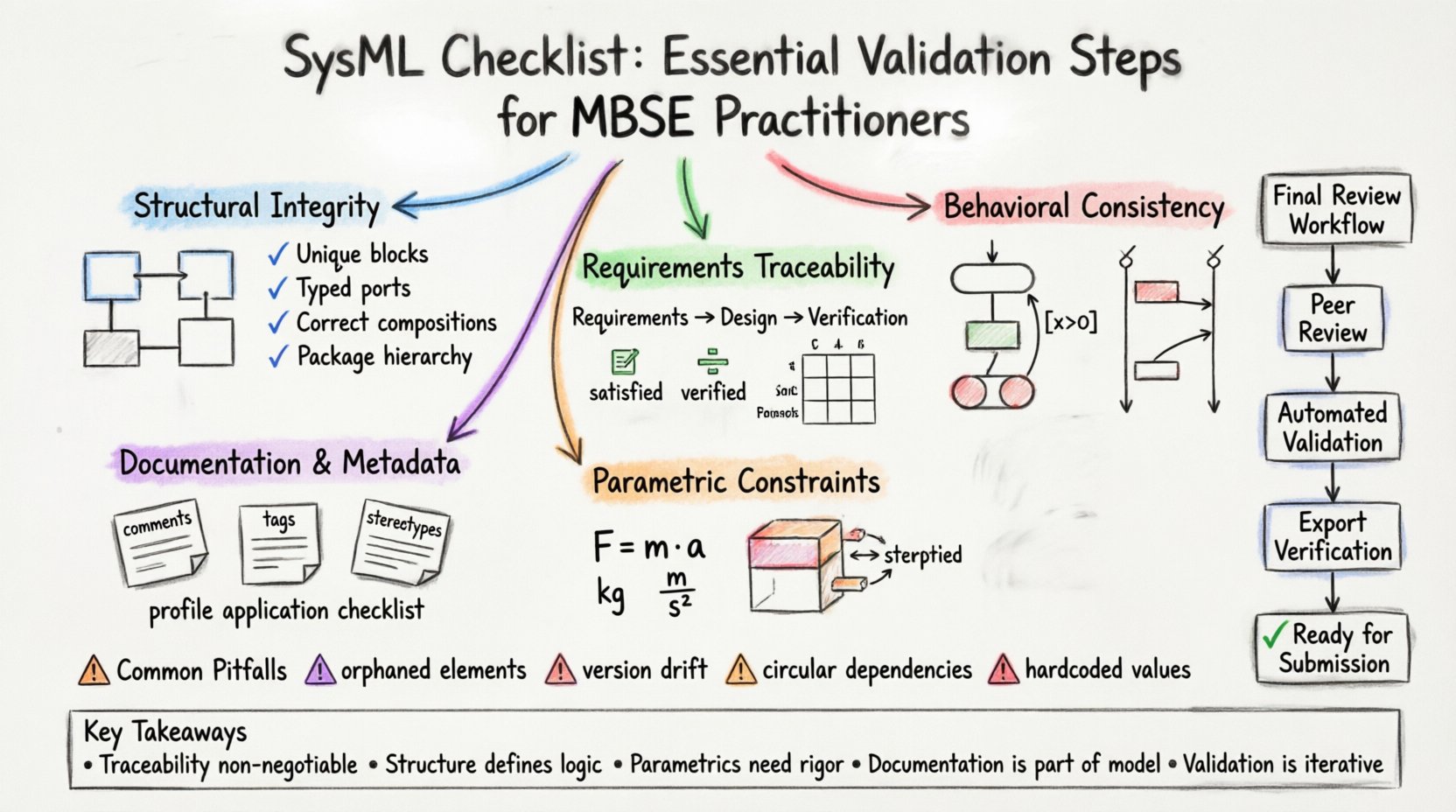
Key Takeaways for Practitioners 🎯
- Traceability is Non-Negotiable: No requirement should exist without a verification path.
- Structure Defines Logic: Errors in block definitions propagate to all diagrams.
- Parametrics Require Rigor: Unit consistency is critical for valid analysis.
- Documentation is Part of the Model: Metadata provides necessary context for future engineers.
- Validation is Iterative: Treat the checklist as a recurring process, not a final gate.
Following these steps ensures the model stands up to scrutiny and serves its purpose as the authoritative source of truth for the system engineering lifecycle.