Systems engineering relies heavily on precision. A model is not just a drawing; it is the single source of truth for design, verification, and implementation. When working with the Systems Modeling Language (SysML), the gap between a rough draft and a production-ready model can determine project success or failure. Ambiguity in diagrams leads to misinterpretation, which cascades into costly rework during the integration phase. This guide provides a rigorous framework to validate your work before it moves to the next stage.
Reviewing a SysML model requires a shift in perspective. You are not just checking for syntax errors; you are verifying logic, traceability, and architectural integrity. Use the following checklist to identify gaps in your model. These questions cover structure, requirements, behavior, and value types. They are designed to surface hidden risks early.
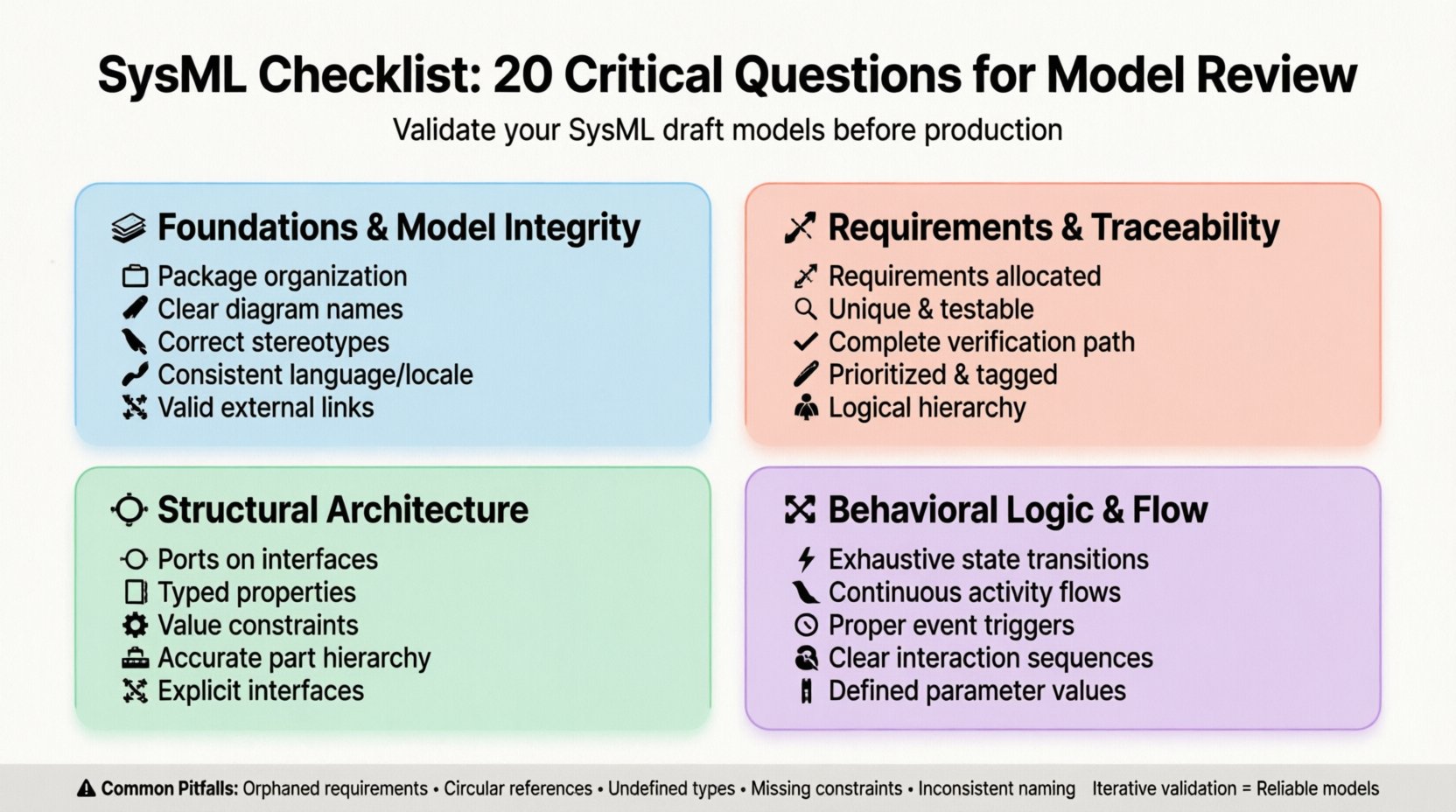
Section 1: Foundations & Model Integrity 🏗️
Before diving into specific diagrams, you must ensure the container for your data is sound. A disorganized model makes navigation difficult and traceability impossible. The first five questions address the structural backbone of the SysML file.
1. Are all packages and namespaces logically organized? 📂
Complex systems require a hierarchical structure. If your model is a flat list of diagrams, traceability will break as the project scales. Check if your packages reflect the system decomposition. Sub-packages should align with subsystems or functional areas. If you find yourself clicking through five layers to find a specific block, the hierarchy is likely too deep. If everything is in the root package, it is too shallow. A balanced tree structure allows for modular development and easier team collaboration.
2. Do diagram names accurately reflect their content? 🏷️
Diagrams are the primary interface for stakeholders. A diagram labeled “System Overview” might contain five different views. This creates confusion. Ensure the title specifies the scope. For example, “Top-Level Block Definition Diagram” is better than “System Structure.” Consistency in naming conventions reduces cognitive load during reviews. Every diagram should be identifiable by its name alone without opening it.
3. Are all elements assigned to the correct stereotypes? 🏷️
Stereotypes define the nature of an element. A block acting as a requirement is semantically incorrect. Verify that every element adheres to the standard SysML profile. Custom profiles should be documented. If you have created a custom stereotype, ensure it is applied consistently. Mismatched stereotypes can break automated checks or validation scripts that rely on type identification. This is a common source of error in large models.
4. Is the model language and locale consistent? 🌍
Global projects often involve teams from different regions. Language settings affect how text is rendered and interpreted. Ensure all text elements use a consistent character set. If your model supports multiple languages, check that translation tags are applied correctly. Ambiguity in units or terminology can lead to manufacturing errors. Verify that date formats and number separators align with the engineering standards used by the downstream teams.
5. Are references to external documents valid? 🔗
Models often link to requirements documents, specifications, or standards. These external references must be maintained. Broken links indicate outdated information. Check every hyperlink within the model. Ensure that the referenced documents are stored in a central repository accessible to all reviewers. If a document has moved or been renamed, the link will fail. A model with broken links is considered incomplete and unreliable.
Section 2: Requirements & Traceability 📝
Requirements are the anchor of the system. Without strong traceability, you cannot prove that the design meets the need. This section focuses on the relationship between what is needed and what is built.
6. Is every requirement allocated to a system element? 🔗
A requirement that floats in the requirement diagram without a target is useless. Traceability must flow from the requirement to the design element. Check if every requirement in the “Satisfy” or “Refine” relationship points to a block or interface. Orphaned requirements suggest scope creep or missing design elements. If a requirement has no satisfying element, it may be obsolete or the design is incomplete.
7. Are requirements unique and unambiguous? 🔍
Review the text of the requirements themselves. Avoid vague terms like “user-friendly” or “efficient.” SysML cannot verify vague text, but humans can. Ensure every requirement is testable. If a requirement cannot be verified through a test case, it is not a valid requirement. Check for duplicate requirements. Multiple requirements stating the same thing waste modeling effort and complicate traceability analysis.
8. Is the verification path complete? ✅
Traceability is a chain: Requirement → Design → Test. Ensure this chain is unbroken. For every requirement, there should be a corresponding verification test case. If the chain stops at the design, you have no way to validate the system. Check the “Verify” relationships. If a requirement is not verified, the system cannot be certified. This is a critical compliance check for regulated industries.
9. Are requirements prioritized and tagged? 🏷️
Not all requirements carry equal weight. In complex systems, trade-offs are necessary. Ensure priority tags are applied to requirements. This helps teams focus on critical features first. If a model lacks prioritization, it is difficult to manage scope changes. Review the metadata associated with requirements. Ensure that criticality levels are defined according to the project standard.
10. Is the requirement hierarchy logical? 🌳
Requirements should be decomposed logically. A parent requirement should be satisfied by the sum of its children. Check if the “Refine” relationships make sense. If a child requirement is more general than the parent, the hierarchy is inverted. Logical decomposition ensures that changes in lower-level requirements do not break higher-level functions. Review the tree structure to ensure it matches the functional architecture.
Section 3: Structural Architecture 🔧
The Block Definition Diagram (BDD) represents the physical and logical structure of the system. This section validates the composition and connections of your blocks.
11. Are ports defined on all interface blocks? 🔌
Ports are the interfaces between blocks. If a block has no ports, it is isolated. Check that every block intended to interact with another has defined ports. Internal block diagrams (IBD) should show flows connecting these ports. If you have a block with no ports but it is connected to others, the model is semantically incorrect. Ensure that flow ports are used for physical signals and standard ports for data.
12. Are part properties typed correctly? 🧱
Properties define the data within a block. Verify that the type of each property is defined. A property cannot exist without a type. If a property is typed as “Integer,” ensure that value constraints are applied if necessary. Missing types lead to ambiguity in data exchange. Check that complex types are defined in value types or nested blocks. Proper typing ensures data integrity during simulation or code generation.
13. Are constraints applied to value properties? ⚙️
Constraints define limits on data. A block might have a mass property, but without a constraint, any mass is valid. Check if physical properties have min, max, and unit constraints. This is crucial for sizing analysis. If a constraint is missing, the model allows invalid configurations. Review the OCL (Object Constraint Language) or built-in constraint tools to ensure boundaries are respected.
14. Is the part hierarchy accurate? 🏗️
Blocks contain parts, which contain other parts. This hierarchy must reflect the physical assembly. Check if the nesting of parts matches the bill of materials. If a part is nested inside a block that does not own it, the relationship is invalid. Ensure that the composition relationships are marked correctly as composite or shared. This distinction affects lifecycle management and memory allocation in derived artifacts.
15. Are interfaces explicitly defined? 🔌
Interfaces decouple blocks from implementation. Check if all interaction points use interfaces. If a block directly connects to another block without an interface, tight coupling is introduced. This makes the system difficult to modify. Verify that interfaces are defined as interface blocks or ports. Ensure that the interface definition is reused across multiple blocks to enforce consistency.
Section 4: Behavioral Logic & Flow 🔄
Behavior diagrams describe how the system operates over time. This section ensures the logic is sound and flows are complete.
16. Are state transitions exhaustive? ⚡
In a state machine, every state must have defined transitions. If a state has no exit, the system hangs. Check for “dead states” where no transition is possible. Ensure that the initial state is connected to the first meaningful state. Review the final states. Every path should ideally lead to a final state. Incomplete transitions indicate missing logic for error handling or edge cases.
17. Are activity flows continuous? 🌊
Activity diagrams show the flow of control and data. Ensure that control flows connect every activity node. If a flow ends abruptly, the activity cannot proceed. Check that object flows have defined types. A flow cannot carry data of an undefined type. Verify that decision nodes have paths for all possible outcomes. Missing paths create logical gaps in the system operation.
18. Are events properly triggered? ⏱️
Events initiate changes in behavior. Check if events are linked to the correct triggers. An event must have a source and a target. If an event is defined but not connected to a transition, it is unused. Ensure that signal events match the signal definition. Mismatched event types can cause simulation failures. Review the timing constraints associated with events to ensure they are realistic.
19. Is interaction sequence clear? 📞
Sequence diagrams show the timing of interactions. Check if messages are sent in the correct order. Verify that lifelines represent the correct blocks. If a message is sent to a non-existent lifeline, the interaction is impossible. Ensure that return messages are included where necessary. Sequence diagrams are critical for understanding asynchronous behavior. If the flow is too complex, consider breaking it into sub-diagrams.
20. Are parameter values defined for parameters? 📊
Parameters allow diagrams to be reusable. Check if all parameters have default values or are mandatory. If a parameter is required but not defined, the diagram cannot be instantiated. Ensure that parameter types match the connected flows. Parameter mismatches cause type errors during execution. Review the parameter interface to ensure it aligns with the system interface definition.
Common Validation Pitfalls ⚠️
Even with a checklist, certain errors recur frequently. The table below summarizes common pitfalls and their recommended checks.
| Pitfall | Impact | Recommended Check |
|---|---|---|
| Orphaned Requirements | Unverified Design | Run Traceability Matrix Report |
| Circular References | Model Corruption | Check Dependency Graph |
| Undefined Types | Simulation Failure | Validate Type Hierarchy |
| Missing Constraints | Invalid Sizing | Review Value Type Properties |
| Inconsistent Naming | Confusion | Standardize Naming Convention |
Implementing these checks requires discipline. It is not enough to run the checklist once. Model quality is an iterative process. As the design evolves, return to these questions. New requirements may invalidate old structural decisions. New behaviors may expose missing ports. Continuous validation prevents technical debt from accumulating.
Adopting this checklist ensures that your SysML model serves its purpose as a reliable specification. It bridges the gap between abstract ideas and concrete implementation. By rigorously applying these 20 questions, you reduce the risk of error and increase the confidence of all stakeholders. A well-reviewed model is the foundation of a successful systems engineering project.