In systems engineering, the complexity of modern technology often surpasses the capacity of human memory to hold the entire architecture at once. To manage this, engineers employ a strategy known as decomposition. SysML (Systems Modeling Language) provides the standard syntax for this process, allowing teams to define components, their relationships, and their interactions without ambiguity. This guide explores the mechanics of component breakdown, focusing on how subsystems link to form a unified system.
Effective decomposition is not merely about splitting a system into smaller pieces. It is about defining boundaries, interfaces, and responsibilities with precision. When done correctly, the model becomes a single source of truth that supports verification, validation, and lifecycle management. Below, we examine the structural elements, diagrammatic representations, and best practices required to build robust SysML models.
🏗️ The Foundation: Understanding Blocks and Decomposition
The fundamental building block of SysML is the Block. In the context of component breakdown, a Block represents a physical or logical unit that has properties, operations, and behaviors. Decomposition involves taking a high-level Block and defining it as a composite of smaller Blocks. This hierarchical approach allows engineers to zoom in on specific details while maintaining the context of the larger system.
Why Decompose?
- Manage Complexity: Breaking a system down reduces cognitive load on the design team.
- Parallel Development: Different teams can work on different subsystems simultaneously.
- Reusability: Standardized components can be reused across different projects.
- Traceability: Requirements can be linked directly to specific components within the hierarchy.
The Anatomy of a Block
Every Block in a SysML model should be clearly defined. A well-structured block includes:
- Properties: Parts that the block contains (e.g., a sensor inside a control unit).
- Operations: Actions the block can perform (e.g., calculate, transmit, store).
- Values: State variables that describe the condition of the block.
- Constraints: Rules that limit the behavior or physical attributes of the block.
📊 Visualizing Structure: Diagram Types
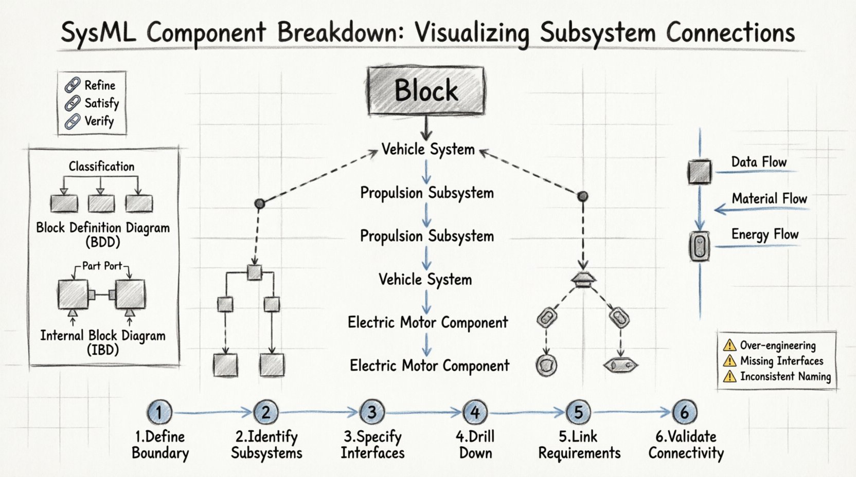
While the underlying data model is consistent, SysML uses different diagram types to visualize aspects of the component breakdown. The two most critical diagrams for structural decomposition are the Block Definition Diagram (BDD) and the Internal Block Diagram (IBD).
BDD vs. IBD: A Structural Comparison
Understanding the distinction between these diagrams is essential for accurate modeling. The BDD defines the type of the block, while the IBD defines the internal wiring and flow of a specific instance.
| Feature | Block Definition Diagram (BDD) | Internal Block Diagram (IBD) |
|---|---|---|
| Purpose | Defines the type, properties, and relationships of blocks. | Defines the internal composition and connectivity of a block. |
| Focus | Classification, generalization, and usage relationships. | Flow of data, material, energy, and signals. |
| Elements | Blocks, Interfaces, Relationships. | Parts, Ports, Connectors, Flow Properties. |
| Use Case | High-level architecture and subsystem inventory. | Subsystem integration and interface specification. |
Using BDD for Hierarchy
In the Block Definition Diagram, decomposition is often shown through composition relationships. A parent block is linked to child blocks, indicating that the parent is made up of the children. This creates a tree structure that mirrors the physical assembly of the system.
- Composition: A strong relationship where the child cannot exist without the parent.
- Association: A looser link between blocks that may exist independently.
- Generalization: Inheritance, where a specialized block derives from a generic block.
🔌 Connecting the Pieces: Interfaces and Ports
Once components are defined, they must communicate. In SysML, communication is managed through interfaces. A Block cannot simply touch another Block; they must interact through defined points. This abstraction ensures that internal implementations remain hidden, adhering to the principle of encapsulation.
Ports: The Entry and Exit Points
Ports are the interface points on a block. They define how a block exposes its functionality to the outside world. There are two primary types of ports:
- Standard Ports: Used to specify a set of provided or required interfaces. This is the most common form in SysML.
- Flow Ports: Used to represent the flow of data, material, or energy. These are critical for defining the physical movement through the system.
Interfaces: The Contract
An Interface in SysML is a set of operations or signals that a block can perform or exchange. It acts as a contract between subsystems. When a Block uses an interface, it promises to provide specific capabilities. When a Block requires an interface, it promises to consume specific inputs.
Key aspects of Interface design include:
- Standardization: Interfaces should be reusable across multiple blocks.
- Abstraction: Interfaces should hide the internal complexity of the subsystem.
- Directionality: Clearly define which side provides the service and which requires it.
🔄 Internal Connectivity: Connectors and Flow
The Internal Block Diagram is where the magic of connection happens. Here, parts (instances of blocks) are linked together using connectors. These connectors represent the physical or logical pathways through which information or resources travel.
Types of Connectors
- Connector: Links two ports to allow them to interact. It enforces interface compatibility.
- Flow Property: Represents the actual movement of something (data, fluid, power) along a connector. It is typed by a value type.
- Reference: Links a part to an external entity or model.
Ensuring Connectivity Integrity
A common error in component breakdown is creating disconnected ports. To maintain model integrity, every port must be connected to at least one other port, unless it is an external boundary. The following checklist ensures connectivity:
- Verify that all required interfaces on a part are provided by a connected part.
- Check that flow properties match the direction of the connector.
- Ensure that value types are compatible between connected flow ports.
- Validate that no circular dependencies exist without a defined control flow.
📈 Managing Hierarchy and Nesting
Systems engineering often involves deep hierarchies. A vehicle subsystem might contain an engine, which contains cylinders, which contain valves. SysML supports nesting, where an IBD can be defined inside a Block. This allows for a drill-down view without losing the parent context.
Best Practices for Deep Nesting
- Limits on Depth: Avoid nesting more than 3-4 levels deep. Beyond this, the model becomes difficult to navigate.
- Interface Propagation: Decide if interfaces should be propagated from the parent to the child or defined locally.
- Boundary Definition: Clearly mark the boundary of the system. This helps in defining what is internal and what is external.
🔗 Requirements and Traceability
Component breakdown is meaningless if it does not serve the requirements of the system. SysML allows direct linking between Requirements and Blocks. This traceability ensures that every component serves a purpose and that every requirement is satisfied by a physical or logical element.
Traceability Paths
- Refine: A high-level requirement is refined into a more specific requirement.
- Satisfy: A block or subsystem satisfies a requirement.
- Verify: A test case verifies that a requirement is met.
When breaking down components, it is vital to map requirements to the specific level of the hierarchy where the work is performed. This ensures that verification activities are aligned with the design.
⚠️ Common Pitfalls in Component Modeling
Even experienced modelers encounter issues when structuring complex systems. Being aware of these common pitfalls can save significant time during the verification phase.
Over-Engineering the Model
Creating a model that is too detailed too soon can lead to rigidity. It is better to start with a high-level view and refine as requirements mature. Adding unnecessary properties or operations early can clutter the model and obscure the main architecture.
Ignoring Interfaces
Defining blocks without defining their interfaces creates a model that cannot be simulated or verified. Every interaction point must be explicit. If a subsystem communicates via a wire, there must be a connector. If it communicates via data, there must be a flow property.
Inconsistent Naming
Consistency is key for readability. A block named ControlUnit in one diagram should not be named CU in another. Use a consistent naming convention that reflects the function of the component rather than just its shape or location.
🛠️ Practical Steps for Effective Breakdown
To implement a successful component breakdown, follow a structured approach. This methodology ensures that the resulting model is robust and scalable.
- Define the System Boundary: Identify what is inside the system and what is outside. Define the top-level block.
- Identify Major Subsystems: Break the top-level block into primary functional groups.
- Specify Interfaces: Define the ports and interfaces required for these subsystems to interact.
- Drill Down: Decompose each subsystem into smaller blocks until the level of implementation is reached.
- Link Requirements: Assign requirements to the appropriate blocks to ensure coverage.
- Validate Connectivity: Run model checks to ensure all ports are connected and flows are valid.
🌐 Collaboration and Views
Large projects involve multiple stakeholders. A single view of the model is rarely sufficient. SysML supports the creation of different views to cater to different audiences, such as software engineers, hardware engineers, and project managers.
- Architectural View: Focuses on the high-level blocks and their relationships.
- Implementation View: Focuses on the detailed IBDs and internal wiring.
- Behavioral View: Focuses on the state machines and activity diagrams associated with the blocks.
By maintaining these distinct views, teams can focus on their specific areas of expertise without being overwhelmed by the entire system’s complexity.
🚀 Future Proofing the Model
Systems evolve. Requirements change, and technologies shift. A well-structured component breakdown allows for easier modifications. When a requirement changes, the impact can be traced through the model to the specific block that needs updating.
Key strategies for future-proofing include:
- Abstraction Levels: Keep high-level models abstract enough to survive changes in implementation technology.
- Standardized Interfaces: Use industry-standard interfaces where possible to ensure compatibility with future tools.
- Documentation: Keep the model documentation up to date. The model is a living document, not a static drawing.
🧭 Final Thoughts on System Cohesion
Creating a cohesive system through SysML component breakdown is a disciplined process. It requires a clear understanding of the hierarchy, a rigorous definition of interfaces, and a commitment to traceability. By visualizing how subsystems connect, engineers can ensure that the final product functions as intended.
The goal is not just to draw boxes and lines, but to create a digital twin that accurately reflects the physical reality. This model serves as the backbone for design, analysis, and verification throughout the product lifecycle. With careful planning and adherence to best practices, the complexity of modern systems becomes manageable.
Remember that the model is a tool for communication. If the breakdown is confusing to the team, it is not effective. Prioritize clarity, consistency, and completeness in every diagram. This approach leads to systems that are not only built correctly but are also easier to maintain and evolve over time.