System Modeling Language (SysML) provides a robust framework for defining complex systems, yet the true power often lies beneath the surface of high-level diagrams. While Block Definition Diagrams (BDD) establish the static taxonomy of a system, the Internal Block Diagram (IBD) reveals the dynamic logic of interaction. Understanding the hidden logic behind internal block structures and port connections is essential for creating models that are not just descriptive, but executable and analyzable.
Many modelers stop at defining blocks and relationships, leaving the internal mechanics ambiguous. This creates a gap between architectural intent and physical realization. A well-structured IBD clarifies how components exchange information, energy, and material. It serves as the contract for subsystem development and the basis for simulation logic.
Understanding the Block Definition vs. Internal Structure 🏗️
The foundation of any SysML model rests on the distinction between what a block is and how it behaves internally. Confusing these two contexts leads to structural errors that propagate throughout the verification process.
- Block Definition Diagram (BDD): Focuses on the classification and relationships between blocks. It answers the question: “What is this part of the system?” This includes inheritance, generalization, and association relationships.
- Internal Block Diagram (IBD): Focuses on the composition and connectivity. It answers the question: “How are the internal parts connected?” This is where the actual logic of data flow and signal exchange resides.
When constructing an internal structure, it is vital to remember that the IBD is a view of the block instance. It does not define new types of blocks but rather exposes the internal ports and connectors of an existing type. This separation of concerns allows teams to validate the architecture without needing to know the specific internal implementation of every sub-part until necessary.
The Anatomy of a Port: Defining Interaction Boundaries 🚦
Ports are the interfaces between a block and its environment, whether that environment is the external system or an internal sub-component. They define the boundary where interaction occurs. Misunderstanding port types is a primary source of modeling errors.
Types of Ports
Ports are categorized based on the nature of the interaction they facilitate. Each category dictates the rules for data exchange and flow direction.
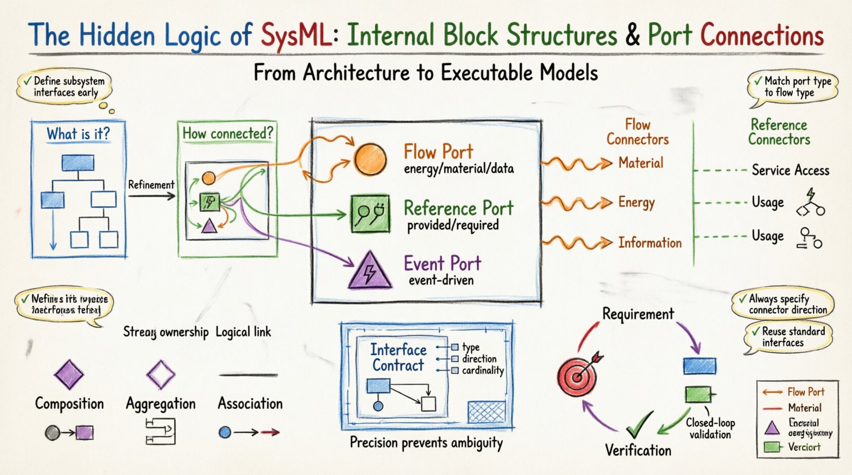
- Flow Ports: Represent the exchange of physical quantities such as energy, material, or data. These are used when modeling the actual movement of a substance or signal through the system.
- Reference Ports: Represent the ability to access or use services provided by another block. They do not imply the movement of a physical quantity but rather a functional capability or service interface.
- Event Ports: (Less common but critical for state logic) Represent the occurrence of a specific event that triggers a state transition or action.
Provided vs. Required Interfaces
Every port must have an associated interface to define the semantics of the connection. The interface acts as a contract between the provider and the consumer of the interaction.
- Provided Interface: The block offers a service or a flow. The port is marked with a “lollipop” symbol.
- Required Interface: The block needs a service or flow to function. The port is marked with a “socket” symbol.
Consistency between the interface type and the port type is mandatory. A flow port cannot connect to a reference port unless there is an implicit conversion defined, which is generally discouraged in rigorous modeling. The logic dictates that a flow of electrical energy requires a flow port, whereas a command signal might utilize a reference port depending on the modeling convention.
Connector Types: Mapping Data and Material Flows ⛓️
Connectors bind ports together, establishing the path for interaction. They define the topology of the system. The choice of connector type influences how the model is interpreted by analysis tools.
Flow Connectors
Flow connectors link flow ports. They are used to model the movement of physical quantities.
- Material Flow: Models physical movement, such as fuel, parts, or fluids.
- Energy Flow: Models power transfer, such as electricity or hydraulic pressure.
- Information Flow: Models data transmission, signals, or telemetry.
When using flow connectors, directionality is key. The arrow indicates the direction of the flow. This allows for the calculation of mass balance, energy balance, and signal latency within the simulation environment.
Reference Connectors
Reference connectors link reference ports. They model the provision of services or capabilities rather than physical movement.
- Service Access: Models the ability to invoke a function on a subsystem.
- Usage: Models the dependency on a specific capability provided by another block.
Unlike flow connectors, reference connectors do not typically carry a physical quantity. They represent a logical dependency. This distinction is crucial when performing dependency analysis or allocation of functions to physical hardware.
Interface Definition: The Contract of Connectivity 📜
An interface in SysML is a set of operations, properties, or signals that define how a block interacts with its environment. It is the blueprint for the port behavior.
- Interface Block: Defines the structure of the interface. It contains properties that represent the data or signals.
- Interface Package: Groups related interfaces for reuse.
When defining an interface, precision is paramount. Vague interfaces lead to ambiguous implementations. Every property within an interface must have a defined type, direction (in/out), and cardinality.
Consider the logic of a communication link. If the interface specifies a “Command” property, the internal logic must support the reception and parsing of that command. If the interface specifies a “Telemetry” property, the internal logic must support the generation of that data.
Structural Relationships: Aggregation and Composition 🧱
Internal structures are not just a flat list of connected parts. They are hierarchical. SysML uses composition and aggregation to define ownership and lifecycle dependencies.
- Composition: Strong ownership. If the parent block is destroyed, the child parts are destroyed. The lifecycle is coupled.
- Aggregation: Weak ownership. The child parts can exist independently of the parent block.
This distinction impacts system reliability analysis. A component that is composed within a safety-critical subsystem must be treated differently than one that is merely aggregated. The model must reflect this reality to support accurate risk assessments.
Comparison of Structural Relationships
| Relationship | Lifecycle Dependency | Visual Notation | Use Case |
|---|---|---|---|
| Composition | Strong (Child dies with Parent) | Filled Diamond | Sub-assemblies, proprietary modules |
| Aggregation | Weak (Child can exist independently) | Empty Diamond | Shared resources, external suppliers |
| Association | None | Line | Logical relationships, references |
Traceability: Linking Structure to Requirements 🎯
A model without traceability is merely a diagram. To ensure the internal logic meets the system needs, every structural element must be linked to a requirement.
- Requirement Allocation: Link a requirement to a specific block or port to show where the need is addressed.
- Verification Mapping: Link a verification method to the internal structure to demonstrate how the connection will be tested.
This creates a closed loop of logic. If a requirement changes, the impact analysis starts at the requirement node and traverses the allocation link to the specific port or connector. This ensures that the hidden logic of the system remains aligned with the defined needs.
Common Modeling Pitfalls and Best Practices 🚧
Even experienced modelers can fall into traps that compromise the integrity of the system architecture. Awareness of these common issues helps maintain model quality.
Issue 1: Over-Abstraction
Creating a single block for an entire subsystem without defining internal ports. This hides the complexity and prevents detailed analysis. Best Practice: Define interfaces at the subsystem boundary early, even if internal details are deferred.
Issue 2: Mixing Flow and Reference
Using a reference port to model a physical signal flow. This confuses the analysis engine regarding the nature of the data. Best Practice: Use Flow ports for signals carrying data or energy. Use Reference ports for service invocations.
Issue 3: Unclear Directionality
Leaving connector direction ambiguous. This leads to errors in simulation. Best Practice: Always define the arrow direction explicitly, matching the physical or logical flow.
Issue 4: Redundant Interfaces
Creating unique interfaces for every connection rather than reusing standard interfaces. This increases maintenance burden. Best Practice: Create a library of standard interfaces for common protocols and data types.
Validation and Verification within the Model ✅
The internal structure serves as the basis for validation and verification activities. The model should support the definition of checks that ensure the logic holds.
- Interface Consistency: Ensure all ports connected to a block match the block’s defined interface.
- Constraint Satisfaction: Apply constraints to properties to ensure values remain within physical limits during simulation.
- Connectivity Checks: Verify that all required ports have a corresponding provided port connected.
By embedding these checks into the modeling environment, the system logic is continuously validated. This reduces the risk of integration errors during the physical build phase.
Advanced Considerations for Complex Systems 🔍
As systems grow in complexity, the internal block structure must evolve to handle scale and abstraction.
- Parameterized Blocks: Allow blocks to be instantiated with different parameters, reducing the need for duplicate diagrams.
- Value Types: Define custom value types for units and properties to ensure consistency across the model.
- State Machine Integration: Link state machines to blocks to define the behavioral logic that governs the ports.
These advanced features allow the model to represent not just the static structure, but the dynamic behavior of the system. This is where the hidden logic becomes fully visible and actionable.
Summary of Structural Logic Principles 📝
Maintaining a rigorous approach to internal block structures ensures the model remains a reliable asset throughout the system lifecycle.
- Separation of Concerns: Keep definitions (BDD) separate from internal connectivity (IBD).
- Interface Discipline: Treat interfaces as contracts that must be strictly adhered to.
- Flow Accuracy: Ensure flow ports and connectors accurately represent physical quantities.
- Traceability: Link every structural element back to a system requirement.
The logic of SysML internal structures is not merely about drawing lines between boxes. It is about defining the precise mechanisms by which a system functions, interacts, and delivers value. A deep understanding of ports, connectors, and blocks transforms a diagram into a digital twin of the system’s operational reality.