In the discipline of Systems Modeling Language (SysML), the sequence in which elements are defined often dictates the success of a project. A frequent error encountered by practitioners is the tendency to define behavior before structure is established. This approach creates a fragile model foundation, leading to rework, ambiguity, and verification challenges. This guide examines the pitfalls of prioritizing behavior over structure and offers a structured path toward robust system definition.
Understanding the Foundation: Structure vs. Behavior 🏗️
Systems engineering relies on the abstraction of complex realities into manageable models. SysML supports two primary dimensions of system description:
Structure: Defines the physical and logical components, their relationships, and interfaces. This includes blocks, parts, ports, and connectors.
Behavior: Defines the dynamic actions, states, and flows that the system performs. This includes state machines, activity diagrams, and sequence diagrams.
When a modeler jumps straight into behavior, they are essentially describing a function without defining the container that executes it. This is akin to writing a script for a play before deciding who the actors are or what the stage looks like. While behavior is critical, it must be anchored to a concrete structural framework.
Many projects struggle because the structural integrity is weak. Without a clear definition of blocks and their interfaces, behavior diagrams become disconnected narratives. The following sections detail specific mistakes and how to correct them.
Mistake 1: Creating State Machines Without Defined Blocks ⏳
One of the most common errors is starting with State Machine Diagrams (STD). A state machine describes how a system transitions between states based on events. However, states must belong to something. That “something” is a block.
The Error: Modelers create a state machine and assign it to a generic “System” block without decomposing that system into sub-blocks.
The Consequence: As requirements evolve, the single block becomes too large to manage. Changes to logic require modifying the top-level block, which impacts all derived behavior.
The Solution: Define the Block Definition Diagram (BDD) first. Decompose the system into logical subsystems. Assign state machines to specific sub-blocks where the logic is relevant.
Consider a propulsion system. If you model the “Engine State Machine” immediately, you must decide if it controls the fuel pump, the ignition, or the exhaust. By defining the Block Structure first, you clarify that the “Fuel Subsystem” block owns the fuel logic, and the “Ignition Subsystem” block owns the spark logic.
Mistake 2: Neglecting Internal Block Diagrams (IBD) 🔄
The Internal Block Diagram is the blueprint of connections. It shows how parts interact through ports and connectors. Skipping this diagram in favor of behavioral views is a critical oversight.
The Error: Relying solely on Sequence Diagrams to show data flow without defining the structural interfaces.
The Consequence: Data flows are defined, but the types of data and the physical interfaces are not. This leads to integration failures later in the lifecycle.
The Solution: Use IBDs to define the flow of information and material. Ensure every port has a defined type (e.g., Data, Signal, Flow).
When structure is defined via IBDs, the behavior diagrams gain context. An activity diagram flow can reference a specific port defined in the IBD. This linkage ensures that the behavior is physically executable.
Mistake 3: Over-Engineering Sequence Diagrams Too Early 📉
Sequence Diagrams (SD) are excellent for detailing interactions between objects over time. However, they are often overused at the beginning of a project when the object structure is not yet stable.
The Error: Creating detailed message sequences between objects that do not yet exist in the Block Definition.
The Consequence: High rework rate. If the structure changes, the sequence diagram often breaks or requires significant modification.
The Solution: Use Sequence Diagrams for refinement. Once the BDD and IBD are stable, use SDs to validate the interaction logic.
Sequence diagrams imply a level of object instantiation that may not be justified in the early phases. Focus on the flow of requirements through the structure first. Use SDs to clarify complex logic once the structural boundaries are clear.
Mistake 4: Ignoring Requirements Traceability 📝
Structure and behavior must serve requirements. A common mistake is creating models that look complete but lack links to the requirements that drove them.
The Error: Building blocks and states without linking them to the Requirement Diagram.
The Consequence: Inability to verify if the model satisfies the customer needs. Verification becomes a manual, error-prone process.
The Solution: Link every significant block and state to a requirement. Use the Requirement Diagram to maintain this link.
Traceability ensures that the model is not just a drawing exercise. It validates that every structural component and behavioral transition has a justification. This is essential for certification and compliance.
Mistake 5: Confusing Parameters and Properties 📊
Properties describe the state of a block (e.g., temperature, voltage). Parameters describe the interface (e.g., input signal, output data). Mixing these up leads to confusion in modeling.
The Error: Treating all data points as internal properties when they should be parameters, or vice versa.
The Consequence: Ambiguity in data flow. It becomes unclear where data originates and where it is consumed.
The Solution: Strictly distinguish between internal state (properties) and external interaction (parameters).
Comparative Analysis of Common Errors
The table below summarizes the difference between the incorrect approach and the recommended approach for key SysML areas.
Area | Common Mistake | Recommended Approach |
|---|---|---|
Diagram Start | Begin with Behavior Diagrams (STD, ACT) | Begin with Structure Diagrams (BDD, IBD) |
Block Decomposition | Single top-level block for all logic | Decompose into subsystems with clear ownership |
Data Flow | Implied in behavior only | Explicitly defined in IBD with typed ports |
Traceability | Added after modeling is complete | Linked during the creation of elements |
Interface Definition | Hidden or vague | Defined via Ports and Interfaces |
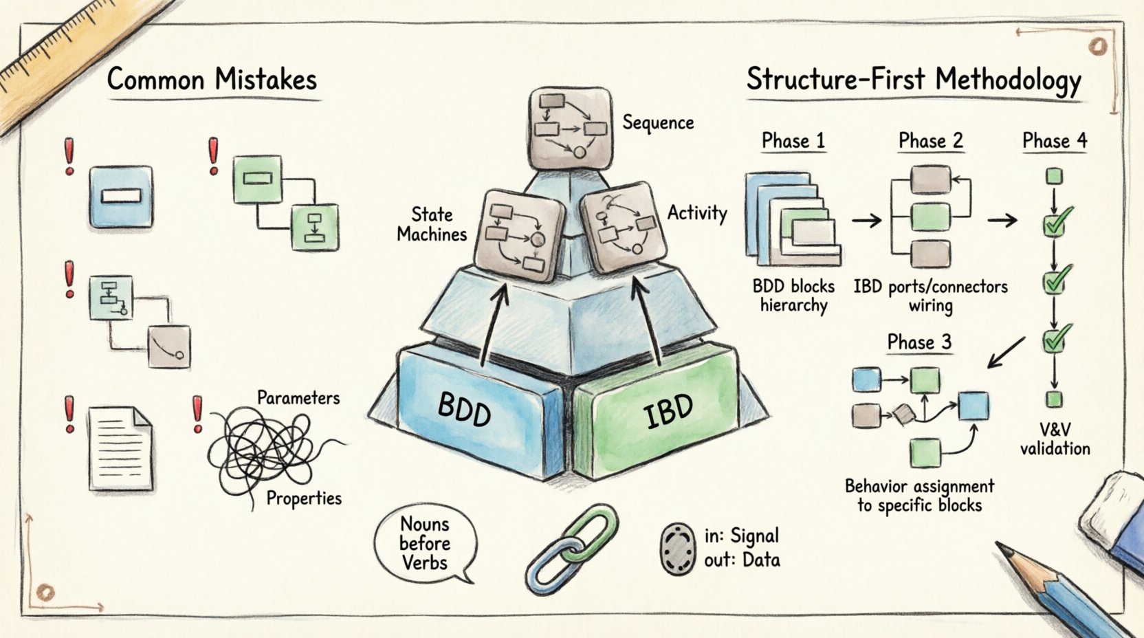
The Structure-First Methodology 🛠️
To avoid these traps, adopt a disciplined workflow that prioritizes the static definition of the system.
Phase 1: Block Definition Diagram (BDD) 🧱
Start by defining the blocks. List the major subsystems. Define the relationships between them (composition, aggregation, association). This establishes the hierarchy.
Identify the top-level system.
Break it down into major components.
Define the types of relationships (e.g., is a part of, uses).
Do not add behavior yet. Focus on the “Nouns” of the system.
Phase 2: Internal Block Diagram (IBD) 🕸️
Once blocks are defined, define how they connect. This is the wiring diagram of the system.
Create an IBD for the top-level block.
Define ports for each block that requires external interaction.
Connect ports with connectors. Ensure the types match.
Define reference properties for items that cross block boundaries.
Phase 3: Behavior Definition 🎬
Now that the stage is set, define the actions. Assign behavior to the specific blocks where it belongs.
Create State Machines for blocks that have distinct modes.
Create Activity Diagrams for blocks that process flows.
Ensure that actions reference the ports defined in Phase 2.
Link behavior to requirements to ensure coverage.
Phase 4: Validation and Verification 🧐
With the model complete, check for consistency. Ensure that the behavior does not contradict the structure. For example, a state machine should not trigger an event on a port that does not exist.
Run model consistency checks if available.
Perform manual reviews of the flow of control.
Verify that all requirements are traced to at least one model element.
Impact on Verification and Validation (V&V) ✅
The structure-first approach significantly aids Verification and Validation. When structure is clear, test cases can be generated based on the physical interfaces. This reduces the risk of finding integration issues late in the development cycle.
Structural Verification: Ensures all parts are accounted for and connected correctly.
Behavioral Verification: Ensures the logic executes as intended given the structural constraints.
Interface Verification: Ensures that signals and data flow correctly between subsystems.
Without a strong structure, V&V becomes a guessing game. You are verifying behavior without knowing if the physical hardware can support it.
Communication Benefits 🗣️
Clear structure improves communication among stakeholders. Engineers, managers, and customers all benefit from a clear view of the system composition.
Engineers: Know exactly which block to implement.
Managers: Understand the scope and boundaries of the work.
Customers: See the deliverables in a tangible way.
Behavior diagrams alone are often too abstract for non-technical stakeholders. Structure diagrams provide the necessary context to understand the scale and complexity of the project.
Long-Term Maintenance 🛠️
Models are living documents. They evolve as the system evolves. A structure-first model is easier to maintain because the core components are stable. Behavior changes frequently, but the structure changes less often.
When a requirement changes, update the behavior first.
If the structure needs to change, the behavior updates automatically because they are linked to the structure.
Refactoring is easier when the dependencies are clear.
Final Thoughts on Model Integrity 🧩
The choice to model structure before behavior is not just a preference; it is a necessity for robust systems engineering. Over-modeling behavior without a structural anchor leads to a fragile artifact that is difficult to verify and maintain.
By adhering to a disciplined workflow that prioritizes Blocks and Internal Block Diagrams, teams can ensure that their models serve as a reliable source of truth. This approach reduces risk, improves clarity, and facilitates better collaboration across the development lifecycle.
Remember, a model is a representation of reality. Reality has structure. Therefore, the model must define structure first. Only then can behavior be accurately described.
Key Takeaways 📌
Always define Blocks (BDD) before defining States or Activities.
Use Internal Block Diagrams to define interfaces and data flow.
Link every model element to a requirement for traceability.
Separate internal properties from external parameters.
Validate the model structure before refining behavior.
Avoid creating Sequence Diagrams until the object structure is stable.
Focus on the “Nouns” (Structure) before the “Verbs” (Behavior).
Adopting these practices will lead to higher quality models and more successful system implementation. The path to a reliable system is paved with solid structural foundations.