Software architecture is the backbone of any robust application. Without a clear structure, codebases quickly become tangled, difficult to maintain, and prone to errors. A full-stack application involves multiple layers, from the user interface to the database, each with distinct responsibilities. Visualizing these structures is essential for clarity and communication among development teams. This guide details how to model layers effectively using UML package diagrams, ensuring your architecture remains organized and scalable.
When developers visualize their system, they create a map that guides future development. UML package diagrams provide a high-level view of the system’s organization. They group related elements into packages, showing how these groups interact. This approach helps in managing complexity by abstracting implementation details. By focusing on boundaries and dependencies, teams can ensure separation of concerns.
Understanding the Architecture 🏛️
Before drawing diagrams, it is crucial to understand the components involved in a full-stack environment. A typical application is divided into horizontal layers. Each layer serves a specific purpose and exposes interfaces to other layers. This separation allows changes in one area without affecting others.
Consider the flow of data and control. A request typically starts at the presentation layer, moves through business logic, and ends at the data access layer. The diagram should reflect this flow. It should not show every class, but rather the major groupings. This abstraction keeps the diagram readable.
- Clarity: Stakeholders can understand the system without reading code.
- Maintainability: New developers can onboard faster with visual guides.
- Communication: Teams can discuss structural changes without ambiguity.
Fundamentals of UML Package Diagrams 📦
A package is a mechanism for grouping elements. In the context of full-stack development, packages often represent modules, namespaces, or architectural layers. The diagram focuses on the relationships between these packages. It does not show internal details like attributes or methods.
The primary relationships in a package diagram include:
- Dependency: One package uses another. This is the most common relationship.
- Association: A structural link between packages.
- Generalization: Inheritance or implementation of interfaces.
When creating a diagram, visibility is key. Packages should expose only what is necessary. Private elements should not be visible outside the package. This enforces encapsulation at an architectural level.
Defining the Full-Stack Layers 🏗️
Modeling a full-stack application requires identifying the standard layers. While specific technologies may vary, the logical structure remains consistent. The following table outlines the core layers and their responsibilities.
| Layer Name | Primary Responsibility | Example Package Name |
|---|---|---|
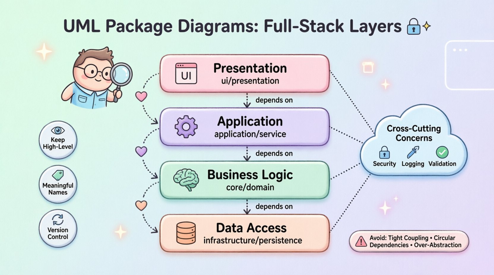
| Presentation | Handling user interaction and display | ui or presentation |
| Business Logic | Implementing core rules and workflows | core or domain |
| Application | Orchestrating business logic use cases | application or service |
| Data Access | Managing persistence and storage | infrastructure or persistence |
Each layer must be modeled as a distinct package. This prevents tight coupling. For instance, the Presentation layer should not know the internal structure of the Database package. It should only interact with the interfaces provided by the Business Logic layer.
Mapping Dependencies and Relationships 🔗
Dependencies define how packages interact. In a well-structured system, dependencies should flow in one direction. This is often called the Dependency Rule. High-level modules should not depend on low-level modules. Both should depend on abstractions.
When modeling this, use arrow lines to indicate usage. The arrow points from the client to the provider. For example, the ui package depends on the service package. The service package depends on the domain package.
- Direct Dependencies: Avoid direct calls between non-adjacent layers.
- Interface Contracts: Define interfaces in the domain package that other layers implement.
- Dependency Injection: Model the wiring of components conceptually.
Consider the relationship between the API and the Backend. The API acts as a gateway. It receives requests and delegates tasks. In the diagram, the API package should depend on the Application layer. It should not bypass the Application layer to talk directly to the Database.
Handling Cross-Cutting Concerns ⚙️
Not all code fits neatly into the main layers. Cross-cutting concerns affect multiple layers. Examples include authentication, logging, and error handling. These should be modeled separately to maintain clarity.
Create a dedicated package for these concerns. This keeps the main layers clean. The main layers depend on the cross-cutting package, but the cross-cutting package does not depend on the specific business logic.
- Security: Authentication and authorization logic.
- Logging: Recording system events and errors.
- Validation: Ensuring data integrity before processing.
When drawing the diagram, show how these packages integrate. Use dashed lines or specific stereotypes to indicate they are support structures. This distinguishes them from functional layers.
Best Practices for Documentation 📝
A diagram is only useful if it is accurate and maintained. Here are strategies to keep your UML package diagrams effective.
- Keep it High-Level: Do not include every class. Group them logically.
- Use Meaningful Names: Package names should describe functionality, not location.
- Limit Depth: Avoid nested packages beyond three levels to prevent confusion.
- Version Control: Store diagrams alongside source code for consistency.
Regularly review the diagram against the codebase. If the code changes, the diagram should change. Outdated diagrams can mislead developers and cause architectural drift.
Maintenance and Evolution 🔄
Software architecture is not static. Requirements change, and the system must adapt. As the application evolves, the package diagram must evolve with it.
When adding a new feature, first update the diagram. This helps identify if the new feature fits the current architecture. If it requires a new layer, create the package structure before writing code.
- Refactoring: If code becomes messy, update the diagram to reflect the new structure.
- Splitting: If a package becomes too large, split it into sub-packages.
- Merging: If two packages are rarely used together, consider merging them.
Adopting a modular approach makes maintenance easier. Each module should have a clear boundary. This allows teams to work on different parts of the system without conflict.
Common Pitfalls to Avoid ⚠️
Even experienced architects make mistakes. Being aware of common errors helps you avoid them.
| Pitfall | Impact | Mitigation Strategy |
|---|---|---|
| Tight Coupling | Changes ripple across the system | Enforce strict dependency rules |
| Circular Dependencies | Build failures and logical errors | Refactor to break the cycle |
| Over-Abstraction | Complexity without benefit | Keep interfaces minimal |
| Ignoring Tests | Unreliable verification | Include test packages in the model |
One specific issue is circular dependencies. This happens when Package A depends on Package B, and Package B depends on Package A. This creates a loop that prevents compilation or causes runtime errors. The diagram should clearly show the direction of flow to prevent this.
Another issue is the God Package. This is a package that contains everything. It makes the system difficult to navigate. Break large packages into smaller, cohesive units.
Final Thoughts on Structured Design 🎯
Modeling layers in a full-stack application is a critical skill for technical leaders. It ensures that the codebase remains manageable as it grows. UML package diagrams offer a standardized way to communicate this structure. They bridge the gap between technical implementation and business requirements.
By following the principles outlined here, teams can build systems that are resilient and easy to understand. The investment in documentation pays off in reduced bugs and faster development cycles. Focus on clarity and consistency in every diagram you create.
Remember that the goal is not perfection, but progress. A diagram that evolves with the project is better than a perfect diagram that stays static. Use these tools to guide your architecture decisions and ensure long-term success.