Software architecture is often compared to city planning. Just as a city requires districts, zones, and roads to function, a complex software system needs logical groupings to remain maintainable. The Unified Modeling Language (UML) offers various tools for this purpose, but few are as essential for high-level organization as the UML Package Diagram. This guide provides a deep dive into the structure, syntax, and strategic application of package diagrams. Whether you are designing a microservices architecture or organizing a monolithic codebase, understanding these diagrams is crucial for clarity and communication.
What Is a UML Package Diagram? 📦
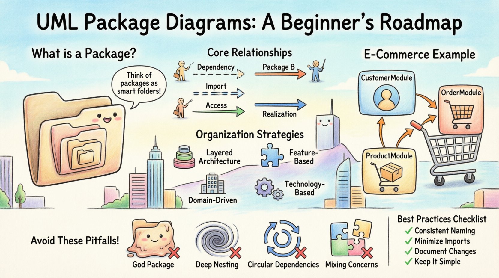
A UML Package Diagram is a structural diagram used to organize elements of a system into groups. These groups are called packages. Think of packages as folders within a file system, but with the added power of defining relationships between them. They are not meant to show individual classes or objects in detail. Instead, they provide a bird’s-eye view of the system’s architecture.
The primary purpose of a package diagram is to manage complexity. As systems grow, the number of classes can become unmanageable. By encapsulating related classes into packages, architects can reduce cognitive load. This allows stakeholders to understand the system’s layout without getting bogged down in implementation details.
Key Characteristics
- Logical Grouping: Organizes elements based on functionality, subsystem, or layer.
- Abstraction: Hides internal details to focus on high-level structure.
- Dependency Management: Visualizes how different parts of the system rely on one another.
- Namespace: Provides a namespace to resolve naming conflicts between elements.
Core Components and Syntax 🛠️
Understanding the visual language of UML is the first step toward creating effective diagrams. A package diagram consists of specific elements, each serving a distinct purpose. There are no arbitrary choices here; every symbol conveys specific structural information.
1. The Package Icon
The fundamental building block is the package itself. Visually, it appears as a rectangle with a tab at the top left corner. This tab gives it the appearance of a folder. The name of the package is placed within the body of the rectangle or on the tab.
- Visibility: While packages usually represent a namespace, their visibility can be public or private depending on the standard being followed.
- Namespaces: Names inside a package are local to that package unless explicitly imported or qualified.
2. Nested Packages
Packages can contain other packages. This allows for hierarchical organization. A large system might have a top-level package named SystemCore, which contains sub-packages like Authentication, Database, and Interface. This nesting helps in defining clear boundaries between subsystems.
3. Notes and Comments
Just like any UML diagram, you can attach notes to packages. These are represented by a small rectangle with a folded corner. They are useful for adding metadata, such as version information, owner details, or specific design rationales.
Relationships Between Packages 🔗
Organizing elements is only half the battle. Understanding how these packages interact is where the real architectural value lies. UML defines specific relationships for packages, distinct from those used for classes. Misinterpreting these relationships can lead to a fragile system architecture.
Dependency (Dashed Line)
The dependency relationship is the most common connection. It indicates that one package requires another to function. If the target package changes, the source package might need to change as well. This is often depicted as a dashed line with an open arrowhead.
- Usage: Package A uses interfaces or classes defined in Package B.
- Direction: The arrow points from the dependent package to the supplier package.
Import (Dashed Line with Double Arrow)
Import is a specific type of dependency. It implies that the elements of the supplier package are brought into the local namespace of the importing package. This is similar to an import statement in programming languages like Java or Python.
Access (Dashed Line with Open Arrow)
Access allows one package to access the public elements of another package. It is similar to dependency but often implies a specific visibility level where the internal implementation details of the supplier remain hidden, while the public API is exposed.
Realization (Solid Line with Hollow Triangle)
While often associated with class diagrams, realization can appear in package diagrams if a package is realizing an interface defined in another package. This is less common but valid in complex layered architectures.
Visibility and Encapsulation 🛡️
Package diagrams are not just about drawing boxes; they are about defining boundaries. Encapsulation is a core principle of software engineering, and packages enforce this at a macro level. You must define how much of a package is visible to the outside world.
Typically, packages operate under a model where:
- Public Elements: Accessible by any other package.
- Private Elements: Accessible only within the same package.
- Protected Elements: Accessible by the package itself and its sub-packages.
When creating a diagram, you should explicitly mark these constraints. This prevents other teams from relying on internal implementation details that might change. It enforces a contract between modules.
Designing a Logical Hierarchy 🌳
Arranging packages is an art form. Poor organization can lead to a tangled web of dependencies that is impossible to refactor. The following table outlines common strategies for organizing packages within a diagram.
| Strategy | Description | Best Use Case |
|---|---|---|
| Layered Architecture | Organizes packages by technical layer (UI, Business Logic, Data). | Monolithic applications with clear separation of concerns. |
| Feature-Based | Organizes packages by business capability (Billing, User Management). | Microservices or modular monoliths. |
| Domain-Driven | Organizes packages by business domain concepts. | Complex systems where business rules are critical. |
| Technology-Based | Organizes packages by technology stack (Database, Web Server). | Infrastructure-heavy systems or legacy integrations. |
Step-by-Step Creation Process 📝
Creating a package diagram is not a task to be rushed. It requires planning and iteration. Follow this logical flow to ensure your diagram adds value rather than clutter.
- Identify Boundaries: Determine the major subsystems of your application. What are the distinct functional areas?
- Group Elements: Place related classes, interfaces, and components into these packages. Avoid scattering related logic across multiple folders.
- Define Dependencies: Draw lines to show how packages interact. Ask yourself: Does this package rely on that one?
- Review for Cycles: Check for circular dependencies. Package A depending on Package B, which depends on Package A, creates a tight coupling that is difficult to maintain.
- Refine Names: Ensure all package names are descriptive. Avoid generic names like
pkg1orutils.
Practical Scenario: E-Commerce System 🛒
To illustrate these concepts, let us consider a hypothetical E-Commerce application. We will break down the architecture into logical packages to demonstrate how a package diagram clarifies the system structure.
Top-Level Structure
At the root, we have a package named CommerceSystem. Inside this, we define three main sub-packages:
- CustomerModule: Handles user registration, login, and profile management.
- OrderModule: Manages cart operations, checkout processes, and order history.
- ProductModule: Controls inventory, catalog details, and pricing.
Dependencies in Action
In this scenario, the OrderModule has a dependency on the ProductModule. When a user places an order, the system must verify product availability. This relationship is drawn as a dependency arrow from OrderModule to ProductModule.
Furthermore, the CustomerModule depends on the OrderModule to retrieve user-specific order history. This creates a clear flow of information.
Internal Packages
We can further subdivide the OrderModule. Inside, we might have PaymentProcessor and ShippingHandler. The OrderModule imports the interfaces from these sub-packages. This shows that the core logic relies on these specific capabilities without knowing their internal implementation.
Common Mistakes and How to Avoid Them ⚠️
Even experienced architects make errors when designing package structures. Being aware of these pitfalls can save significant refactoring time later.
1. The “God Package”
Avoid creating a single package that contains everything. If you have a package named AllTheThings, you have failed to organize your system. This makes the diagram unreadable and the codebase unmanageable.
2. Deep Nesting
While nesting is useful, going too deep (e.g., A > B > C > D > E) creates confusion. Limit your depth to three or four levels. If you need more, reconsider your hierarchy.
3. Circular Dependencies
As mentioned earlier, circular dependencies are a code smell. If Package A imports Package B, and Package B imports Package A, you create a loop. This often happens when two modules need to share common entities. The solution is usually to extract the shared entities into a third, shared package.
4. Mixing Concerns
Do not mix technical concerns with business logic. A package should not contain both database connection logic and user interface logic unless there is a specific reason. Keep technical layers separate from business layers.
Package Diagrams vs. Other UML Diagrams 📊
It is easy to confuse package diagrams with other structural diagrams. Understanding the distinction ensures you use the right tool for the job.
| Diagram Type | Focus | When to Use |
|---|---|---|
| Package Diagram | High-level organization and namespace. | System architecture overview, module boundaries. |
| Class Diagram | Static structure of classes and attributes. | Database schema design, detailed logic flow. |
| Component Diagram | Physical components and their interfaces. | Deployable units, library structures. |
| Component Diagram | Physical components and their interfaces. | Deployable units, library structures. |
While Class Diagrams dive deep into attributes and methods, Package Diagrams stay high. Use Package Diagrams when you need to explain the system to a stakeholder who does not need to see every variable. Use Class Diagrams when you are handing off code to developers.
Best Practices for Maintainability 🔄
A diagram is a living document. It must evolve as the system does. Here are some guidelines to keep your package diagrams useful over time.
- Consistent Naming: Use a standard naming convention (e.g.,
PascalCasefor packages). This reduces ambiguity. - Minimize Imports: Only import what is strictly necessary. Use qualified names when possible to reduce dependency clutter.
- Document Changes: If a dependency changes, update the diagram immediately. An outdated diagram is worse than no diagram at all.
- Use Profiles: If working with specific technologies (like Java or .NET), use UML profiles to extend the notation appropriately without breaking the standard.
- Keep it Simple: If a diagram has more than 50 packages, it is likely too complex. Break it down into sub-diagrams.
Frequently Asked Questions ❓
Can I use package diagrams for documentation?
Yes. They are excellent for architectural documentation. They provide a map for new team members to understand the system layout quickly.
Are package diagrams executable?
No. They are static representations. They describe structure, not behavior. You cannot run code from a package diagram.
How do I handle third-party libraries?
Represent third-party libraries as packages. You can mark them as external or use a specific stereotype to indicate they are not under your control. This clarifies which parts of the system you own versus which you consume.
What if my system changes frequently?
Focus on the stable parts of your architecture. If the boundaries change weekly, a package diagram might be too rigid. In agile environments, keep the diagram abstract and update it during major architectural sprints.
Can packages overlap?
Generally, packages should be distinct namespaces. Overlapping namespaces can lead to naming conflicts. If elements belong to two domains, create a shared package that both can access.
Conclusion ✅
The UML Package Diagram is a foundational tool for managing software complexity. It allows architects to visualize the skeleton of a system, ensuring that dependencies are clear and boundaries are respected. By following the principles outlined in this guide, you can create diagrams that not only document your system but also improve its design.
Remember that a diagram is a means of communication. If your team cannot understand the structure within five minutes, the diagram has failed its purpose. Prioritize clarity, consistency, and logical grouping. With practice, you will find that organizing your system into packages becomes second nature, leading to cleaner code and more resilient architecture.
Start by mapping out your current system. Identify the logical boundaries. Draw the connections. Review for cycles. This process will reveal hidden complexities and guide you toward a more robust design. The effort invested in the diagram pays dividends in the maintainability of the code.
Use this roadmap as a reference. Revisit the sections on relationships and visibility as your projects grow. The principles of organization remain constant, even as the technology stack evolves. Keep your packages clean, your dependencies explicit, and your architecture clear.