Software architecture relies heavily on clear communication between stakeholders, developers, and maintainers. At the heart of this communication lies the Unified Modeling Language (UML). Among the various diagram types, the Package Diagram stands out as a critical tool for organizing complex systems. This guide provides a detailed examination of how to construct, refine, and utilize package diagrams effectively. We will explore the theoretical underpinnings, practical application, and structural best practices required to model software systems with precision.
Understanding the Foundation of Package Diagrams 🧱
A Package Diagram represents a view of the system architecture by grouping related elements into logical containers known as packages. Unlike class diagrams which focus on individual object relationships, package diagrams operate at a higher level of abstraction. This abstraction is essential for managing complexity in large-scale software projects.
The primary purpose of this diagram type is to visualize the organization of code, components, and subsystems. It helps answer fundamental questions regarding the structure of the application:
- Which components interact with one another?
- How is the system divided into manageable sections?
- Where are the boundaries between different layers of the architecture?
By defining these boundaries early, teams can establish contracts between modules. This reduces tight coupling and facilitates independent development cycles. Each package can represent a namespace, a subsystem, a library, or a specific business domain.
Core Concepts and Definitions 📚
Before constructing a diagram, it is necessary to understand the specific elements involved. A package diagram is not merely a collection of boxes; it is a representation of relationships and dependencies.
1. Packages 📁
Packages serve as the primary structural unit. They act as namespaces to prevent naming conflicts and organize elements logically. A package can contain:
- Other packages (nesting).
- Classes.
- Interfaces.
- Use Cases.
- Components.
Nesting packages allows for a hierarchical structure. For example, a top-level “Core” package might contain sub-packages for “Database”, “Security”, and “Network”. This hierarchy mirrors the directory structure of the actual codebase.
2. Relationships 🔗
The strength of a package diagram lies in how packages relate to one another. These relationships define the flow of information and control within the system.
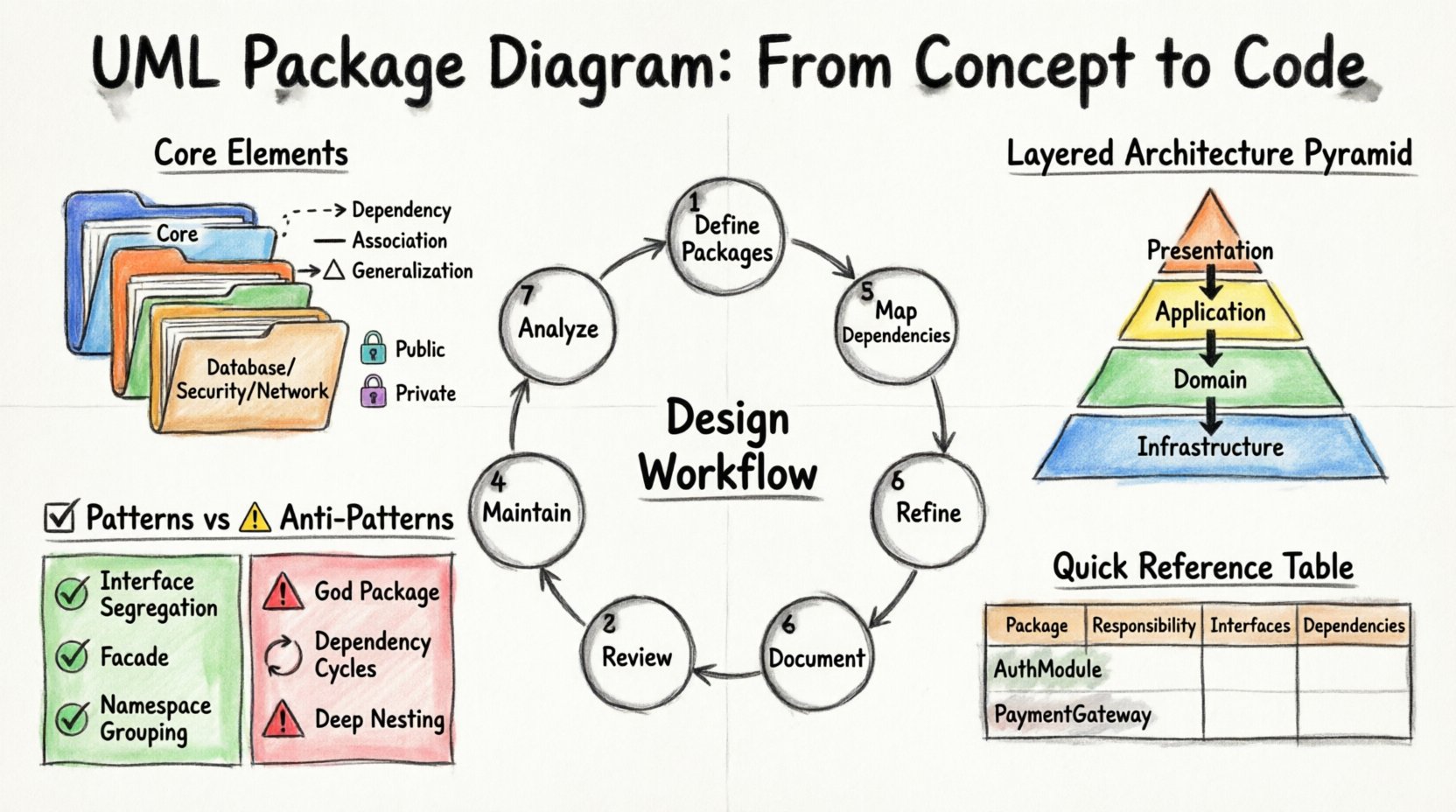
- Dependency: One package requires another to function. This is a “uses” relationship. Changes in the supplier package may affect the client package.
- Association: A structural link where one package holds an instance or reference to another.
- Generalization: A relationship indicating that one package is a specialized version of another (inheritance).
- Realization: Typically used when a package implements an interface defined in another package.
3. Visibility 🕵️
Just like in object-oriented programming, visibility controls what is accessible from outside a package. Packages define public and private elements. A package marked as public exposes its contents to external consumers, while a private package restricts access to internal implementation details only.
Planning the Architecture 🗺️
Creating a package diagram is not a task to be rushed. It requires a strategic approach to ensure the resulting structure aligns with business goals and technical constraints.
Step 1: Identify Business Domains 🏢
Begin by mapping the business capabilities. What functions does the system perform? Group these functions into logical domains. For instance, a retail system might have “Order Processing”, “Inventory Management”, and “Customer Relations”. These become your initial candidates for packages.
Step 2: Determine Cohesion and Coupling 🧩
High cohesion means elements within a package are closely related. Low coupling means dependencies between packages are minimized. This is the golden rule of architecture.
- High Cohesion: Keep related data and logic together. If two classes are always used together, they likely belong in the same package.
- Low Coupling: Minimize dependencies. If Package A depends on Package B, ensure Package B does not depend on Package A unless necessary.
Step 3: Define Layering 🏗️
Most enterprise systems follow a layered architecture. Common layers include:
- Presentation Layer: User interfaces and interaction logic.
- Application Layer: Business logic and workflow management.
- Domain Layer: Core business entities and rules.
- Infrastructure Layer: Database access, file systems, and external services.
Visualizing these layers in a package diagram clarifies the direction of dependencies. Typically, higher layers depend on lower layers, but never the reverse.
Designing the Diagram Structure 🎨
Once the planning phase is complete, the actual modeling begins. The goal is to create a clear visual representation that developers can interpret without ambiguity.
Step 1: Draft the Top-Level View 🖼️
Start with the highest level of abstraction. Draw the main packages that represent the major subsystems. Avoid filling this view with too much detail. The goal is to provide a map of the entire landscape.
Step 2: Refine Internal Structures 🔍
After establishing the top level, drill down into specific packages. Expand complex packages into their constituent sub-packages. This iterative refinement prevents the diagram from becoming cluttered.
Step 3: Map Dependencies 📉
Draw arrows to indicate relationships. Use standard notation for different relationship types:
- Dashed arrow with an open arrowhead for Dependency.
- Solid line for Association.
- Triangle for Generalization.
Ensure that arrows point from the client (user) to the supplier (used). This visual cue immediately reveals where dependencies exist.
Step 4: Validate Against Rules ✅
Review the diagram against architectural constraints. Check for:
- Circular dependencies between packages.
- Violations of layering rules.
- Overly broad packages that contain unrelated elements.
- Missing interfaces that should mediate access.
Managing Complexity with Tables 📊
When dealing with intricate systems, textual descriptions can be ambiguous. A structured table can clarify the rules governing package interactions.
| Package Name | Responsibility | Public Interfaces | Dependencies |
|---|---|---|---|
| AuthModule | Handles user login and session management | ValidateUser, CreateSession | Database, LogModule |
| PaymentGateway | Processes financial transactions | ChargeCard, Refund | AuthModule, Notification |
| ReportingEngine | Generates analytics and summaries | GenerateReport, ExportCSV | DataWarehouse |
This table format complements the visual diagram by providing specific details about interfaces and responsibilities that cannot always be drawn clearly.
Common Patterns and Anti-Patterns 🚦
Experienced architects recognize recurring patterns. Understanding these helps in making better design decisions.
Recommended Patterns ✅
- Interface Segregation: Separate large interfaces into smaller, role-specific packages. This prevents clients from depending on methods they do not use.
- Facade: Create a package that acts as a simplified interface to a complex subsystem. This reduces the number of dependencies visible to external packages.
- Namespace Grouping: Group all related classes under a single namespace package to avoid global namespace pollution.
Common Pitfalls ⚠️
- The God Package: A package that contains too many unrelated classes. This usually indicates a failure to separate concerns.
- Dependency Cycles: Package A depends on B, and B depends on A. This makes deployment and testing difficult because neither can exist without the other being compiled or initialized first.
- Deep Nesting: Creating too many levels of sub-packages (e.g., A/B/C/D/E). This creates confusion and makes navigation difficult.
- Hidden Implementation: Exposing internal classes that should remain private. This forces other packages to rely on implementation details rather than stable interfaces.
Refining Dependencies and Relationships 🔍
The accuracy of the dependency lines is crucial. Ambiguity here leads to runtime errors and maintenance nightmares.
Dependency Types Explained 📝
Not all dependencies are created equal. Some are stronger than others.
- Usage: The most common type. One package uses the functionality of another. This is often transient.
- Import: One package explicitly imports definitions from another. This is common in module-based systems.
- Access: Direct access to internal elements. This should be avoided in favor of public interfaces.
Handling Cycles 🔄
Dependency cycles are the most significant challenge in package design. A cycle occurs when Package A depends on B, and B depends on A.
To resolve this:
- Identify the classes causing the circular reference.
- Extract the shared logic into a new, intermediate package.
- Have both original packages depend on the new package instead of each other.
This technique is known as the “Dependency Inversion Principle”. It ensures that high-level modules do not depend on low-level modules, but both depend on abstractions.
Documentation and Maintenance 📝
A package diagram is a living document. As the software evolves, the diagram must evolve with it.
Version Control for Models 📂
Just like source code, model files should be stored in version control systems. This allows teams to track changes, revert to previous states, and understand the history of architectural decisions.
Integrating with Code 🛠️
While this guide focuses on manual design, automated tools often exist to generate diagrams from code. However, relying solely on auto-generation can be problematic. It often results in cluttered diagrams that do not reflect the intended logical architecture.
Manual oversight is necessary to:
- Group classes into logical packages that may not match the physical file structure.
- Define interfaces that do not yet exist in the code.
- Document architectural constraints that are not visible in the source.
Review Cycles 🔄
Establish a review process for the diagram. Before any major code change, the architecture should be reviewed.
- Does the new feature fit within an existing package?
- Does the change introduce new dependencies?
- Are the naming conventions consistent across all packages?
Best Practices for Naming 🏷️
Clear naming conventions are vital for readability. A package name should be descriptive and consistent.
- Use Singular or Plural Consistently: Do not mix “User” and “Users”. Choose one style and stick to it.
- Avoid Abbreviations: Unless they are industry standard, write out full words. “Pkg” is less clear than “Package”.
- Reflect Purpose: Instead of “Module1”, use “PaymentProcessing”. The name should explain the function.
- Match Code Structure: Where possible, align package names with the directory structure to reduce cognitive load for developers.
Advanced Considerations 🚀
For complex systems, additional considerations come into play.
Physical vs. Logical Packages 🖥️
Distinguish between logical organization and physical deployment.
- Logical: How the code is structured in the developer’s mind. Focus on cohesion and separation of concerns.
- Physical: How the code is deployed. Focus on file paths, libraries, and server configurations.
While a logical package might contain multiple physical files, a physical deployment unit might aggregate several logical packages. The diagram should primarily focus on the logical view, as it is more stable over time.
Extensibility 🧩
Design packages with future growth in mind. Will this module need to interact with a new system next year? Leave interfaces open for extension. Use abstract packages that can be implemented by multiple concrete modules.
Summary of Workflow 🔄
To summarize the process of creating a robust package diagram:
- Analyze Requirements: Understand the business domain and functional needs.
- Define Packages: Group elements based on cohesion.
- Map Dependencies: Draw relationships and check for cycles.
- Refine Structure: Apply layering and hierarchy.
- Document Interfaces: Specify public contracts.
- Review and Validate: Check against architectural rules.
- Maintain: Update the diagram as the system evolves.
Following this workflow ensures that the resulting model serves as a reliable blueprint for development. It reduces ambiguity, guides coding standards, and facilitates communication across the team.
Final Thoughts on Modeling 🎯
The effort invested in creating a well-structured package diagram pays dividends during the development and maintenance phases. It provides a shared vocabulary for the team and a clear roadmap for the system’s evolution. By adhering to principles of cohesion, coupling, and clear documentation, architects can build systems that are resilient and adaptable.
Remember that the diagram is a tool for thought, not just a deliverable. Use it to explore design options and identify potential issues before writing a single line of code. This proactive approach leads to higher quality software and fewer surprises down the line.