In the complex world of software architecture, clarity is the currency of success. As systems grow in size and complexity, managing code organization becomes a critical challenge. This is where the UML Package Diagram serves as an essential tool for architects and developers. It provides a high-level view of the system’s structure, organizing elements into logical groups known as packages. This guide explores the mechanics, benefits, and best practices for designing effective package diagrams without relying on specific tools.
🤔 What is a UML Package Diagram?
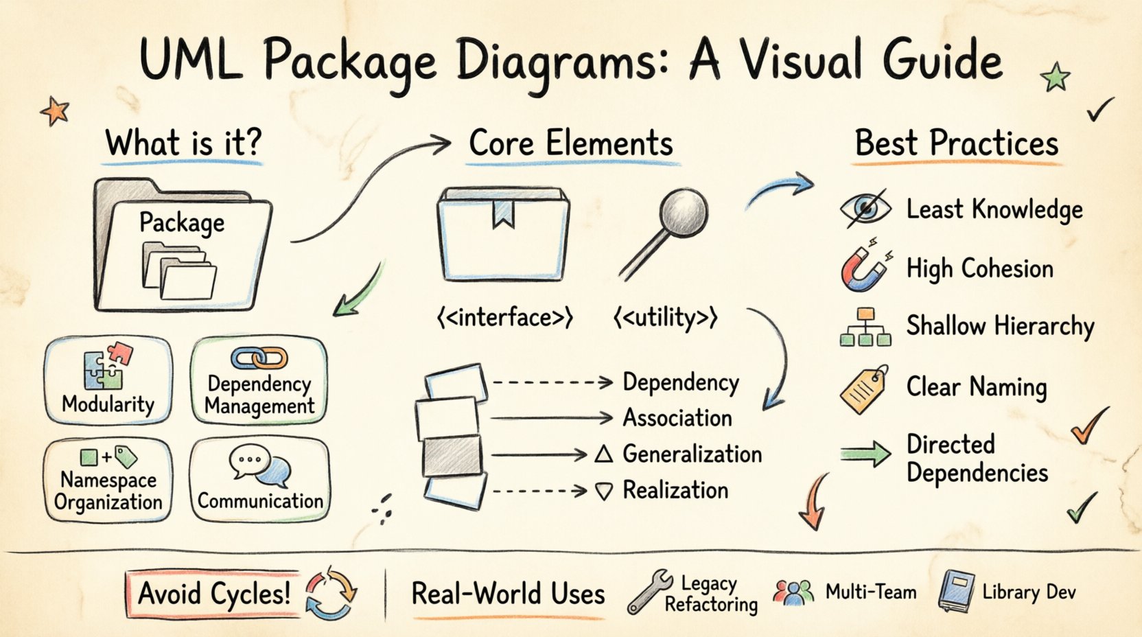
A UML Package Diagram is a type of structure diagram in the Unified Modeling Language (UML). Its primary purpose is to show the organization of a system into logical groupings. Think of it as a map of folders and subfolders, but for software components. It allows teams to visualize how different parts of a system interact at a macro level.
Unlike a Class Diagram, which focuses on individual classes and their relationships, a Package Diagram abstracts away the details. It focuses on the boundaries between major modules. This abstraction is vital for large-scale projects where understanding the entire codebase at once is impossible.
Key Objectives
- Modularity: Break down complex systems into manageable units.
- Dependency Management: Visualize how modules rely on one another.
- Namespace Organization: Define scopes for identifiers to prevent conflicts.
- Communication: Provide a common language for stakeholders to discuss architecture.
🧩 Core Elements of a Package Diagram
To construct a meaningful diagram, one must understand the building blocks. These elements form the vocabulary of package modeling.
1. Packages
A package is a mechanism for organizing elements into groups. It acts as a namespace. In a visual representation, packages are often drawn as large rectangles with a tab in the upper-left corner.
- Root Package: The top-level container for the entire system.
- Sub-packages: Packages contained within other packages to create hierarchy.
- Leaf Packages: Packages that contain no other packages, often housing classes or interfaces.
2. Nodes and Interfaces
While packages are the containers, they interact through defined boundaries.
- Interfaces: Define the contract a package exposes to others. They specify what operations are available without revealing internal implementation.
- Nodes: Represent physical or logical computing resources where software components are deployed. While more common in deployment diagrams, they can appear in package diagrams to show where a package resides.
3. Stereotypes
Stereotypes extend the notation to provide specific meaning. They are typically written in guillemets (<< >>). Common stereotypes in package modeling include:
- <<namespace>>: Indicates a grouping of elements.
- <<subsystem>>: A package that represents a major functional component of the system.
- <<framework>>: A reusable design with a specific set of responsibilities.
🔗 Understanding Relationships and Dependencies
The true power of a package diagram lies in how packages relate to each other. These relationships define the flow of information and control. Mismanagement of these links leads to tight coupling and fragile systems.
Types of Relationships
UML defines four primary types of relationships between packages. Understanding the distinction is crucial for accurate modeling.
| Relationship | Symbol | Meaning | Use Case |
|---|---|---|---|
| Dependency | Dashed arrow with open head | One package uses another for functionality. | A utility package is required by the business logic package. |
| Association | Solid line | Structural connection between instances. | Two packages have a long-term structural link. |
| Generalization | Solid line with hollow triangle | One package is a specialized version of another. | Inheritance of structure or interface definitions. |
| Realization | Dashed line with hollow triangle | One package implements the interface of another. | A concrete package fulfills an abstract contract. |
Dependency Direction
Dependencies are directional. If Package A depends on Package B, changes in B may require changes in A. Ideally, dependencies should flow in a single direction to avoid circular logic. A circular dependency occurs when Package A depends on B, and B depends on A. This creates a logical loop that complicates compilation and maintenance.
🎨 Visual Notation and Symbols
Consistency in visual notation ensures that anyone reading the diagram understands the architecture immediately. While specific tools may vary slightly, the standard UML notation remains consistent.
- Package Icon: A rectangle with a folded corner tab. The name is placed inside or below the tab.
- Dependencies: A dashed line ending in an open arrowhead pointing to the provider package.
- Visibility: Use symbols to denote access levels:
- +: Public (visible to all packages).
- –: Private (visible only within the package).
- #: Protected (visible within the package and subclasses).
🛠️ How to Create a Package Diagram
Creating a diagram is a systematic process. It requires analysis, grouping, and validation. Follow these steps to build a robust model.
Step 1: Analyze the System Requirements
Before drawing, understand what the system needs to do. Review the functional requirements to identify major capabilities. Look for distinct areas of responsibility. For example, a banking system might naturally separate into modules for Authentication, Transactions, and Reporting.
Step 2: Identify Logical Groupings
Group related classes, interfaces, and components together. These groups become your packages. Ask yourself:
- Do these elements share a common purpose?
- Do they change together often?
- Do they provide a specific service to the rest of the system?
Step 3: Define Boundaries and Interfaces
Once groups are identified, define the public interface of each package. What does this package expose to others? What does it keep hidden? This step enforces encapsulation principles.
Step 4: Map Dependencies
Draw the lines connecting the packages. Ensure arrows point from the dependent package to the package being used. Review the map for:
- Cycles or loops.
- Unnecessary cross-links.
- Congested areas where too many packages interact.
Step 5: Refine and Validate
Review the diagram with the development team. Does it match the actual code structure? Is the naming convention clear? Refine the diagram iteratively as the system evolves.
🚀 Best Practices for Package Design
Designing a package diagram is not just about drawing boxes; it is about designing a maintainable system. Adhering to established principles improves the quality of the architecture.
1. Follow the Principle of Least Knowledge
Reduce the number of direct interactions between packages. A package should know as little as possible about the internal details of other packages. Use interfaces to mediate access. This reduces coupling and increases flexibility.
2. Maintain High Cohesion
Elements within a single package should be closely related. If a package contains unrelated classes that do not interact frequently, the cohesion is low. High cohesion means the package has a single, well-defined responsibility.
3. Avoid Deep Hierarchies
While nesting packages helps organize, excessive depth makes navigation difficult. Limit the depth of the package tree. If a package contains more than three levels of sub-packages, consider flattening the structure or reorganizing the logic.
4. Use Clear Naming Conventions
Naming is critical for readability. Use descriptive names that reflect the content.
- Good: PaymentProcessing, UserAuthentication, DataValidation
- Poor: Module1, Core, Utils, GroupA
5. Keep Dependencies Directed
Aim for a directed acyclic graph (DAG). Dependencies should flow from high-level components to low-level components. For example, the User Interface layer should depend on the Business Logic layer, which depends on the Data Access layer. The reverse should not be true.
🆚 Package Diagram vs. Other UML Diagrams
Understanding when to use a Package Diagram compared to other diagrams prevents redundancy and confusion. Each diagram serves a specific purpose in the modeling lifecycle.
| Diagram Type | Focus | When to Use |
|---|---|---|
| Package Diagram | High-level organization and modularity | During system design and architectural planning. |
| Class Diagram | Static structure of classes and attributes | During detailed design and implementation phases. |
| Component Diagram | Physical software components and their interfaces | When modeling deployable units or libraries. |
| Deployment Diagram | Hardware topology and software deployment | When planning infrastructure and server configurations. |
⚠️ Common Mistakes to Avoid
Even experienced architects can fall into traps when modeling. Being aware of these pitfalls helps maintain a clean and useful diagram.
1. Over-Specification
A package diagram should not be a Class Diagram in disguise. Avoid adding class attributes or methods inside package boxes. Keep the view abstract. If you need to show classes, use a separate Class Diagram.
2. Ignoring Cycles
Circular dependencies are the enemy of modular design. If Package A imports Package B, and Package B imports Package A, the build process becomes unstable. Refactor the code to break the cycle, often by extracting shared interfaces into a third package.
3. Inconsistent Granularity
Some packages may contain thousands of classes while others contain only two. This imbalance suggests a mismatch in how responsibilities are divided. Aim for packages of similar size and complexity.
4. Static Snapshots
A diagram created once and never updated becomes a liability. As the system evolves, the diagram must evolve. Treat the diagram as living documentation that requires maintenance.
🌐 Real-World Application Scenarios
Package diagrams are not theoretical concepts; they solve real problems in software development.
Scenario 1: Legacy System Refactoring
When inheriting a large, monolithic system, a package diagram helps map the existing structure. It identifies tightly coupled modules that need to be decoupled. It serves as a baseline for migration strategies.
Scenario 2: Multi-Team Development
In large organizations, different teams own different parts of the system. A package diagram defines the boundaries of ownership. Team A owns the Auth package; Team B owns the Reporting package. The interfaces between them become the contract for collaboration.
Scenario 3: Library Development
When creating a reusable library, package diagrams define the public API. They show which parts of the library are stable and intended for external use versus internal implementation details.
📊 Metrics for Package Health
To ensure the architecture remains robust, measure specific metrics derived from the package diagram.
- Coupling Between Objects (CBO): The number of other packages a package depends on. Lower is generally better.
- Response For Package (RFC): The set of methods that can be called in response to a message sent to the package.
- Afferent Coupling (Ca): The number of other packages that depend on this package.
- Efferent Coupling (Ce): The number of packages that this package depends on.
High efferent coupling indicates a package that is too invasive. High afferent coupling indicates a package that is critical and stable. The goal is to balance these to maintain flexibility and stability.
🔄 Evolution of Package Structure
Software is not static. As requirements change, the package structure must adapt. This process is known as refactoring the architecture.
Identifying Smells
Look for signs that the current package structure no longer fits:
- Mixed Concerns: A package handling both UI and Database logic.
- God Package: A package that contains almost everything.
- Isolated Packages: A package that no other package interacts with.
Refactoring Steps
- Analyze: Use static analysis tools to find dependencies.
- Plan: Design the new package structure.
- Move: Relocate classes and files to new packages.
- Verify: Run tests to ensure behavior has not changed.
- Update: Update the diagram to reflect the new reality.
📝 Summary
The UML Package Diagram is a fundamental instrument for managing complexity in software engineering. It transforms a tangled web of code into a structured map of responsibilities. By organizing elements into packages, defining clear interfaces, and managing dependencies, architects can build systems that are easier to understand, test, and maintain.
Remember that the diagram is a tool for thought. It aids in communication and planning. It does not replace the code, but it guides the creation of high-quality code. Focus on clarity, consistency, and adherence to architectural principles. Avoid the temptation to over-complicate the visual representation. Keep the hierarchy shallow, the dependencies directed, and the naming descriptive.
Whether you are starting a new project or analyzing a legacy system, the skills gained from mastering package modeling will pay dividends in the longevity and stability of your software. Use the guidelines, tables, and best practices outlined here to construct diagrams that stand the test of time.