Software architecture relies heavily on clear communication. Among the various visual tools available, the UML package diagram stands out as a critical instrument for depicting the organizational structure of a system. These diagrams show how different modules, namespaces, or components relate to one another at a high level. However, a diagram that is too complex or poorly structured becomes a source of confusion rather than clarity. When team members struggle to interpret a package diagram, the risk of miscommunication increases, and technical debt accumulates.
This guide explores the essential strategies for creating UML package diagrams that remain readable over time. We focus on structural integrity, naming consistency, dependency management, and visual organization. By adhering to these principles, you ensure that your documentation serves its purpose: guiding development and supporting long-term maintenance without becoming an obstacle.
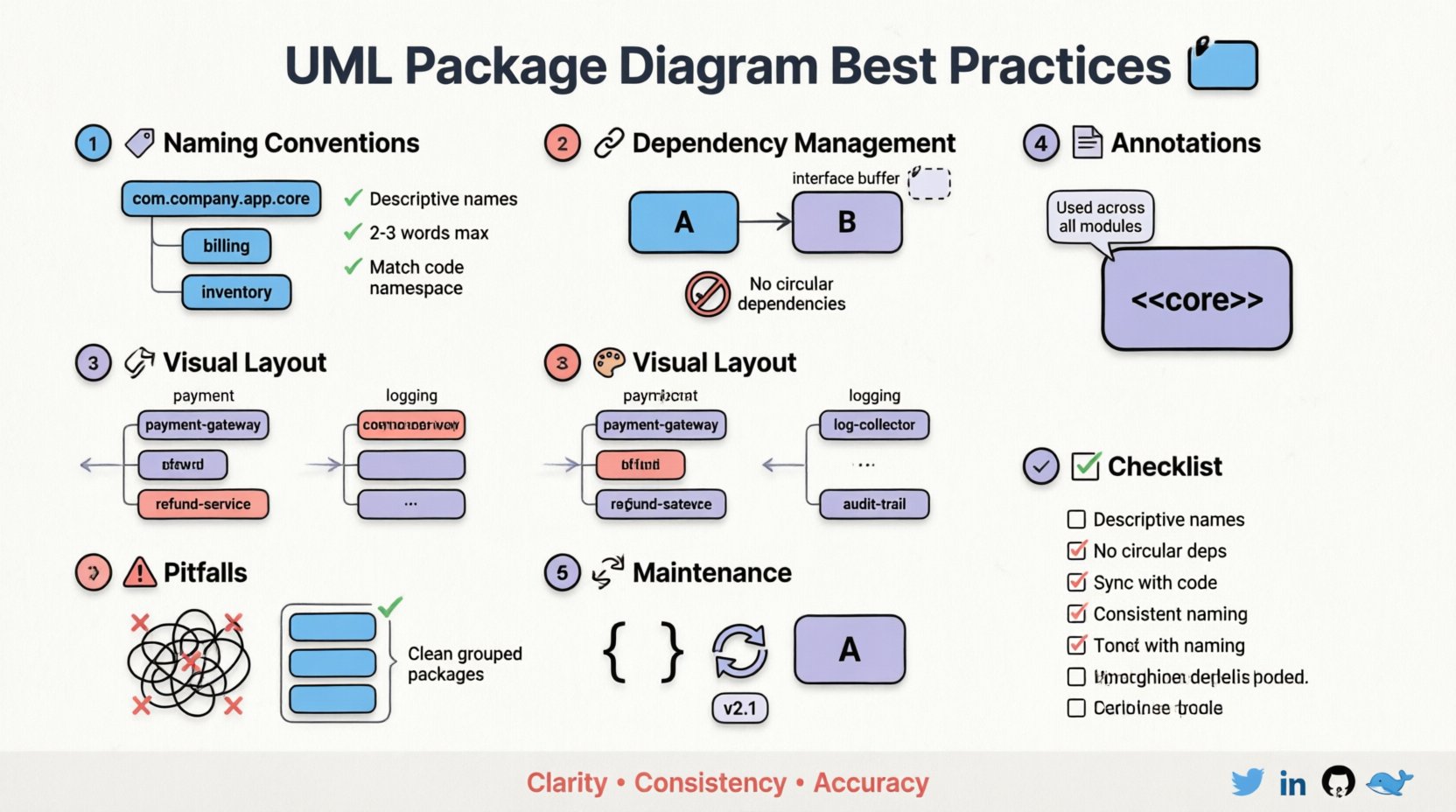
🏷️ 1. Establishing Robust Naming Conventions
The foundation of a maintainable diagram lies in how you name your packages. Names act as the primary identifiers for developers navigating the architecture. Ambiguous or inconsistent naming leads to uncertainty about where specific logic resides or what a component actually does. A standardized naming strategy reduces cognitive load and accelerates onboarding for new team members.
🔹 Hierarchical Naming Structures
Packages should reflect the logical hierarchy of the system. Avoid creating a flat structure where dozens of packages sit at the same level. Instead, use a nested approach that mirrors the business domain or technical layers.
- Domain-Driven Naming: Use business terms that the team understands. For example,
billingorinventoryare clearer thanmodule_aorcore_logic. - Layer-Based Naming: Distinguish between different architectural layers. Prefixes or suffixes can help, such as
domain,service, andinfrastructure. - Namespace Consistency: Ensure that the package name matches the namespace in the codebase. If the diagram shows
payment, the code should ideally live within a corresponding namespace.
🔹 Case and Formatting Standards
Consistency in formatting prevents visual clutter and makes scanning easier. Decide on a convention and enforce it across all diagrams.
- CamelCase vs. SnakeCase: Choose one style for package names. CamelCase (e.g.,
PaymentGateway) is common in code, while snake_case (e.g.,payment_gateway) is often preferred in file systems. Stick to the one used in your repository. - Length Constraints: Keep names concise. Long names force diagrams to expand horizontally, breaking layout balance. Aim for 2-3 words maximum.
- Avoid Acronyms: Unless an acronym is universally understood by every stakeholder, write out the full term.
APIis fine;CRUDmight confuse someone not familiar with the term.
| ❌ Poor Practice | ✅ Good Practice | Reason |
|---|---|---|
pkg1 |
user_authentication |
Descriptive and meaningful |
new_module_v2 |
order_processing |
Stable name regardless of version |
com.company.app |
com.company.app.core |
Logical nesting structure |
🔗 2. Managing Dependencies and Coupling
The relationships between packages define the flow of information and control. In a package diagram, these are typically represented by dependencies. Uncontrolled dependencies lead to tight coupling, making the system fragile and difficult to modify. Managing these connections is central to keeping the diagram readable.
🔹 Dependency Directionality
Dependencies should generally flow from higher-level abstractions to lower-level implementations. This principle, often referred to as the Dependency Inversion Principle, keeps core logic insulated from specific details.
- Arrow Direction: The arrow head points to the dependency. If Package A uses Package B, the arrow goes from A to B.
- Control Flow: Avoid circular dependencies. If Package A depends on B, and B depends on A, the diagram becomes a loop that is hard to reason about. Break these loops by introducing an interface or an intermediate package.
- Import vs. Use: Distinguish between packages that are strictly imported for type definitions versus those that are called for runtime logic. Use stereotypes to label these relationships.
🔹 Reducing Visual Noise
Too many lines connecting packages create a “spaghetti” effect. This obscures the actual architecture. To mitigate this:
- Group Related Dependencies: If multiple classes in Package A depend on multiple classes in Package B, represent the dependency at the package level rather than drawing lines for every single class connection.
- Use Interfaces: Introduce interface packages that act as buffers. Other packages depend on the interface, not the implementation package.
- Limit Fan-Out: A package should not depend on too many other packages. If it does, consider refactoring the logic into smaller, cohesive units.
| Dependency Type | Visual Representation | Maintainability Impact |
|---|---|---|
| Direct Implementation | Standard Open Arrow | High Risk: Changes ripple quickly |
| Interface Contract | Open Arrow + “<<use>> | Low Risk: Implementation can swap |
| Circular | Looping Arrows | Critical: Hard to resolve logic |
🎨 3. Visual Organization and Layout
Even with perfect naming and dependency management, a diagram can fail if the visual layout is chaotic. The goal is to guide the reader’s eye naturally through the system’s structure. This requires deliberate spacing, alignment, and grouping.
🔹 Spatial Grouping
Visually group packages that belong together. While UML allows for explicit grouping constructs (like frames), simple spatial proximity is often sufficient for package diagrams.
- Functional Clusters: Place all payment-related packages near each other. Place all logging utilities in a distinct cluster.
- Logical Zones: Use invisible boundaries or white space to separate concerns. For instance, keep the user interface packages on one side and the database packages on the other.
- Read Order: Arrange the diagram so that the flow of data or control follows a natural reading direction, typically top-to-bottom or left-to-right.
🔹 Avoiding Clutter
Every element on a diagram should serve a purpose. Remove unnecessary details that do not contribute to the high-level understanding.
- Hide Internal Details: Do not list every single class inside a package on the diagram unless the internal structure is the focus. Use the package rectangle to represent the boundary.
- Minimal Labels: Do not add text to dependency lines unless the relationship is non-standard (e.g., a specific type of inheritance or binding).
- Consistent Spacing: Ensure equal padding between packages. Uneven spacing looks unprofessional and makes it harder to scan.
📝 4. Documentation and Annotations
A diagram is a visual summary, but it cannot capture every nuance. Annotations and stereotypes provide the necessary context without cluttering the visual space. They explain the “why” behind the structure.
🔹 Using Stereotypes
Stereotypes allow you to extend the standard UML notation to fit your specific domain. They add semantic meaning to packages and relationships.
- Define Standard Stereotypes: Agree on a set of stereotypes your team will use. Common examples include
<<core>>,<<external>>, or<<test>>. - Consistent Usage: Ensure that
<<interface>>is used consistently across all diagrams. Do not mix<<api>>and<<interface>>for the same concept.
🔹 Annotations and Notes
Use notes to explain complex constraints or specific rules that apply to a package.
- Scope Specificity: Attach notes to the specific package they apply to, not floating in the middle of the diagram.
- Constraint Rules: If a package cannot depend on another, state this in the notes. This prevents developers from creating forbidden dependencies.
- Version Information: If a diagram represents a specific version of the architecture, include a version note in the header or footer.
🔄 5. Maintenance and Versioning
Software evolves. Requirements change, and code refactors. A diagram that is accurate today will be outdated tomorrow if not maintained. Treat the diagram as living documentation, not a one-time artifact.
🔹 Synchronization with Code
The most critical rule of UML package diagrams is accuracy. If the code changes and the diagram does not, the diagram loses all value.
- Update Triggers: Define clear triggers for updating the diagram. Major refactors, new modules, or architectural shifts should mandate an update.
- Automated Generation: Where possible, use tools that can generate diagrams from code or metadata to ensure synchronization.
- Review Process: Include diagram updates in the definition of done for significant features. Ensure the reviewer checks the diagram against the new code.
🔹 Version Control for Diagrams
Just like code, diagrams should be stored in version control systems. This allows teams to track changes over time and revert if a change was detrimental.
- Commit Messages: When updating a diagram, write a commit message explaining the structural change, not just “update diagram”.
- Diff Analysis: Review the differences between versions to understand how the architecture has evolved.
⚠️ 6. Common Pitfalls to Avoid
Even experienced architects can fall into traps that degrade diagram quality. Being aware of these common pitfalls helps in proactively avoiding them.
- Over-Engineering: Trying to make the diagram look perfect rather than functional. A rough sketch that conveys structure is better than a polished but confusing one.
- Mixing Levels of Abstraction: Do not show class-level details in a package diagram. Keep the focus on the package boundaries.
- Ignores Negative Dependencies: Sometimes, the absence of a dependency is more important than its presence. Document what should not connect.
- Static Thinking: Designing the diagram as a fixed entity rather than an evolving map. Architecture is dynamic; the diagram should reflect that reality.
🛡️ 7. Checklist for Readability
Before finalizing a UML package diagram, run through this checklist to ensure it meets maintainability standards.
- ☑️ Are all package names descriptive and consistent?
- ☑️ Are there any circular dependencies?
- ☑️ Is the layout logical and easy to follow?
- ☑️ Are stereotypes used consistently?
- ☑️ Is the diagram synchronized with the current codebase?
- ☑️ Are there unnecessary details cluttering the view?
- ☑️ Are annotations clear and specific?
- ☑️ Is the file stored in version control?
🚀 Conclusion on Architecture Stability
Maintaining readable UML package diagrams is an investment in the longevity of your software project. It requires discipline in naming, careful management of dependencies, and a commitment to keeping the documentation current. When done correctly, these diagrams become a reliable reference that reduces friction during development and onboarding. They clarify the boundaries of responsibility and ensure that the system’s structure remains understandable as it grows.
By following the practices outlined above, you create a visual language that supports the team rather than hindering it. Focus on clarity, consistency, and accuracy. These principles form the backbone of effective software documentation and contribute directly to a healthier, more maintainable codebase.