Software architecture relies on clear visual communication. When modeling complex systems, choosing the right Unified Modeling Language (UML) diagram type is critical for clarity and maintenance. Two frequently confused constructs are the Package Diagram and the Component Diagram. While both deal with grouping and structure, their specific purposes, notations, and use cases differ significantly. Selecting the correct tool depends on the level of abstraction required and the specific architectural questions being answered.
This guide provides a deep analysis of both diagram types. We will explore their definitions, structural elements, and the scenarios where each excels. By the end, you will have a clear framework for deciding which diagram to deploy during your design phase. 🎯
Understanding the Package Diagram 📦
The Package Diagram is a structural diagram that organizes elements of the model into groups or namespaces. It is primarily used to manage complexity by breaking down large systems into smaller, manageable units. In many object-oriented methodologies, packages correspond to logical groupings of classes, interfaces, and other model elements.
Core Characteristics
- Logical Grouping: Packages act as containers for related model elements. They do not represent executable code directly but rather organizational structures.
- Namespace Management: They help resolve naming conflicts. Elements within different packages can share names without collision.
- Dependency Management: They define relationships between groups of classes, such as import, dependency, and association relationships.
- High-Level Abstraction: They provide a macro view of the system’s structure without detailing internal class implementations.
Key Symbols and Notation
- Package Icon: Represented by a folder icon with a tab at the top left.
- Dependency Arrow: A dashed arrow pointing from the dependent package to the package being used.
- Import/Access: Indicates that a package can access the public elements of another package.
Primary Use Cases
- Organizing Large Codebases: When a system grows, packages prevent the model from becoming a tangled web of classes.
- Defining Module Boundaries: They outline which parts of the system rely on others, establishing clear boundaries for development teams.
- Visualizing Compilation Units: In many languages, packages map directly to directories or libraries used during compilation.
- Documentation Strategy: They serve as a table of contents for the system architecture, helping developers navigate the design.
Understanding the Component Diagram 🧩
The Component Diagram focuses on the physical or logical implementation units of a system. Unlike packages, components often represent deployable units, libraries, or runtime entities. They emphasize the contract between a system and its environment through interfaces.
Core Characteristics
- Implementation Focus: Components represent executable parts of the system, such as JAR files, DLLs, or executables.
- Interface Definition: They explicitly define provided and required interfaces (ports) that dictate how components interact.
- Deployment Context: They can show how components are deployed onto nodes or hardware infrastructure.
- Runtime Behavior: They model the system’s state at runtime, focusing on how parts connect and communicate.
Key Symbols and Notation
- Component Icon: A rectangle with the stereotype <<component>> and two small rectangles on the top left.
- Interface (Lollipop): A circle representing a provided interface.
- Interface (Socket): A half-circle representing a required interface.
- Connector Lines: Solid lines indicating assembly connections between provided and required interfaces.
Primary Use Cases
- Microservices Architecture: Ideal for defining services as discrete, deployable components.
- Third-Party Integration: Showing how external libraries or APIs are consumed by internal components.
- System Deployment: Visualizing the mapping of software components to physical hardware nodes.
- Interface Contracts: Ensuring different teams build compatible components by defining strict input/output contracts.
Comparative Analysis: Package vs. Component 🆚
While both diagrams organize system elements, their intent and granularity differ. The following table outlines the technical distinctions to aid in selection.
| Feature | Package Diagram | Component Diagram |
|---|---|---|
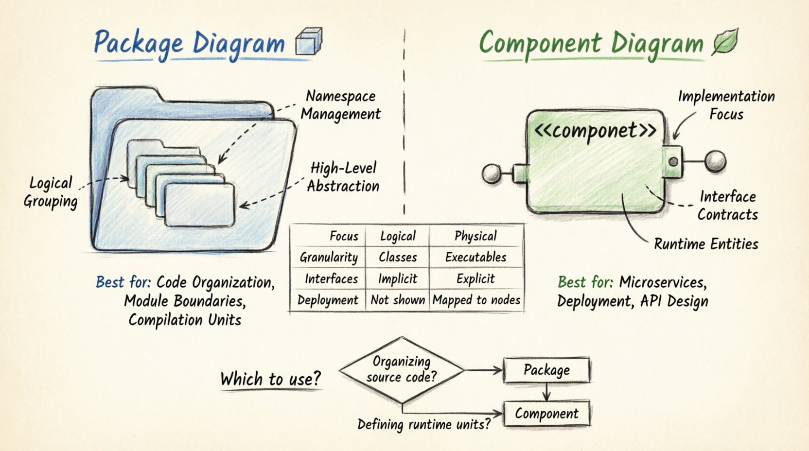
| Primary Focus | Logical organization and namespaces | Physical implementation and interfaces |
| Granularity | High-level (Classes grouped together) | Lower-level (Executable units) |
| Interfaces | Implicit (via class visibility) | Explicit (Ports and Interfaces) |
| Execution | No execution semantics | Represents runtime entities |
| Deployment | Usually not shown | Often mapped to nodes or hardware |
| Dependencies | Logical dependencies | Physical or Assembly dependencies |
| Best For | Source code structure | System integration and deployment |
When to Use a Package Diagram 📂
Select the Package Diagram when your primary concern is the organization of the codebase and the logical relationships between classes. It is most effective during the early design phases or when refactoring existing systems.
Specific Scenarios
- Refactoring Large Systems: If you are moving classes between folders to improve cohesion, the Package Diagram is the blueprint.
- Team Collaboration: When multiple teams work on different modules, packages define the boundaries of responsibility.
- Dependency Analysis: If you need to check if Module A depends too heavily on Module B, this diagram visualizes those links clearly.
- Namespace Clarity: In languages with complex namespace resolution, packages prevent naming collisions and ambiguity.
Using a Package Diagram helps maintain a clean structure. It allows architects to see the “skeleton” of the application without getting bogged down in the details of individual methods or runtime states. It answers the question: “How is the code organized?”
When to Use a Component Diagram 🛠️
Choose the Component Diagram when you need to describe the runtime architecture, deployment strategy, or interface contracts. It is essential for integration planning and infrastructure design.
Specific Scenarios
- System Integration: When connecting different subsystems, components define the exact interfaces needed for communication.
- Cloud Deployment: If mapping services to cloud instances or containers, components represent the deployable artifacts.
- API Design: For defining the public contracts of services that other systems will consume.
- Legacy Modernization: When wrapping legacy code into modern components, the diagram shows how the old and new interact.
The Component Diagram answers the question: “How does the system run and interact?” It is particularly useful when the physical constraints of the environment (like network latency or hardware limits) influence the design.
Common Mistakes and Best Practices ⚠️
Even experienced architects can confuse these diagrams. Avoiding common pitfalls ensures your documentation remains accurate and useful.
Pitfalls to Avoid
- Overlapping Responsibilities: Do not try to force a Package Diagram to show runtime behavior. Keep it logical.
- Ignoring Interfaces: In Component Diagrams, failing to define provided/required interfaces leads to vague integration plans.
- Excessive Detail: Do not list every class inside a package. Keep the view high-level to maintain readability.
- Inconsistent Notation: Ensure your team agrees on the symbols used. Inconsistency creates confusion.
Best Practices
- Consistent Naming: Use clear, descriptive names for both packages and components. Avoid generic terms like “Module1”.
- Layering: Organize packages into layers (e.g., Presentation, Business Logic, Data Access) to enforce separation of concerns.
- Versioning: Keep diagrams synchronized with the codebase. Outdated diagrams are worse than no diagrams.
- Modularity: Design components to be loosely coupled. High coupling makes the system fragile and hard to maintain.
Integration with Other UML Diagrams 🔗
Neither diagram exists in isolation. They play a crucial role in the broader UML ecosystem.
Relationship with Class Diagrams
Package diagrams often contain Class Diagrams. A Package acts as a folder for Class Diagrams, while a Component Diagram may aggregate Class Diagrams to show implementation details. This hierarchy allows you to drill down from high-level architecture to specific logic.
Relationship with Deployment Diagrams
Component Diagrams frequently pair with Deployment Diagrams. Once components are defined, Deployment Diagrams show where they run. This combination bridges the gap between software design and infrastructure operations.
Relationship with Sequence Diagrams
Component Diagrams define the static structure of interactions, while Sequence Diagrams define the dynamic flow of messages between those components. Together, they provide a complete picture of system behavior.
Maintenance and Evolution 🔄
Software is never static. As requirements change, diagrams must evolve. A robust modeling strategy includes processes for updating these diagrams.
- Change Management: When a package is split or merged, update the diagram immediately to reflect the new structure.
- Interface Stability: In Component Diagrams, minimize changes to provided interfaces. Changing them breaks dependent systems.
- Documentation Cycles: Schedule regular reviews of architecture diagrams. Ensure they match the current codebase.
- Automated Generation: Whenever possible, generate diagrams from code or use tools that sync with version control to reduce manual drift.
Decision Framework for Architects 🧭
To make a final decision, ask these guiding questions during your design process.
Questions for Package Diagrams
- Are we organizing source code?
- Do we need to manage namespaces?
- Is the focus on logical grouping of classes?
- Are we defining module boundaries for developers?
Questions for Component Diagrams
- Are we defining runtime units?
- Do we need to specify interfaces explicitly?
- Are we planning deployment or infrastructure?
- Is the focus on integration and contracts?
If the answer to the first set is predominantly “Yes,” choose the Package Diagram. If the second set is the priority, the Component Diagram is the correct tool.
Summary of Architectural Modeling 📝
Selecting between a Package Diagram and a Component Diagram depends on the specific architectural lens you are applying. The Package Diagram excels in managing logical structure and code organization, serving developers who need to navigate the codebase. The Component Diagram excels in defining runtime behavior, interfaces, and deployment, serving integrators and infrastructure planners.
By understanding the distinct strengths of each, you can create documentation that is both accurate and actionable. Clear diagrams reduce ambiguity, improve collaboration, and ensure that the system remains maintainable as it grows. Use the logical view for structure and the component view for implementation. This dual approach provides a comprehensive understanding of the software architecture.
Remember that diagrams are communication tools. Their value lies in how well they convey intent to the team. Whether you choose packages for organization or components for implementation, clarity should always be the guiding principle. 🚀