


Software architecture is the backbone of robust application development, yet creating detailed Unified Modeling Language (UML) diagrams can often be a tedious, syntax-heavy process. The emergence of AI-Assisted UML Class Diagram Generators has transformed this workflow, allowing developers, students, and architects to move from abstract ideas to professional-grade technical diagrams seamlessly. This tutorial explores how to leverage an AI-powered, 10-step wizard to create, validate, and export UML class diagrams without needing deep expertise in PlantUML syntax.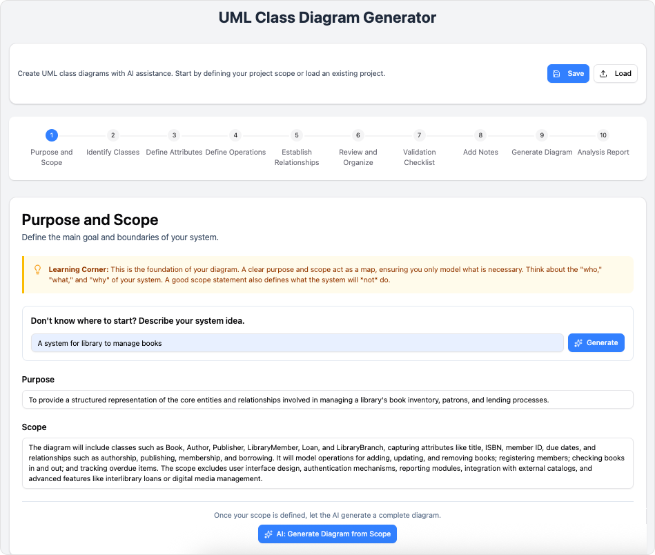
Key Concepts
Before diving into the workflow, it is essential to understand the core components that drive this technology. Familiarizing yourself with these terms will maximize the utility of the tool.
- UML Class Diagram: A static structure diagram that describes the structure of a system by showing the system’s classes, their attributes, operations (or methods), and the relationships among objects.
- AI-Assisted Scoping: The capability of the tool to interpret high-level natural language prompts (e.g., “a library management system“) and automatically generate a structured scope, suggested classes, and relationships.
- PlantUML: An open-source tool used to generate diagrams from plain text language. While powerful, it requires learning specific syntax. This generator abstracts that complexity, offering a visual interface that compiles down to PlantUML code.
- Validation Checklist: An automated system that reviews the design against software engineering best practices to identify missing types, unconnected classes, or circular dependencies before export.
Guidelines: The 10-Step Workflow
The AI-Assisted UML Generator utilizes a logical, linear wizard to ensure no critical design aspect is overlooked. Follow these steps to build a complete architectural document.
Phase 1: Inception and Structure
Step 1: Purpose and Scope
Begin by defining the boundaries of your system. You can input a high-level idea manually, or leverage the AI integration to generate a comprehensive purpose statement. This sets the context for the entire diagram, ensuring the AI understands the domain logic for subsequent suggestions.
Step 2: Identify Classes
List the primary entities within your scope. For a rigorous design, identify the nouns in your scope statement (e.g., “User,” “Order,” “Product”). If you are unsure, the tool can analyze your scope and propose necessary classes for you.

Phase 2: Defining Details
Step 3: Define Attributes
Flesh out your classes by specifying data fields. Define properties, visibility (public, private, protected), and data types. Precision here ensures that the final code generation matches the intended data structure.
Step 4: Define Operations
List the behaviors associated with each class. These are the methods or functions the objects can perform. Clear operation definitions help in visualizing the functional responsibilities of each component.
Step 5: Establish Relationships
This is the core of the class diagram. Map out how classes interact using standard UML relationships: associations, inheritance (generalization), composition, and aggregation. Accurate relationship mapping is crucial for understanding system coupling and dependencies.

Phase 3: Review and Validation
Step 6: Review and Organize
Perform a consolidated review of the entities created so far. This visual step allows you to ensure consistency across class names and relationship directions before finalizing the structure.

Step 7: Validation Checklist
Run the automated validation suite. This step checks for common errors such as orphaned classes (entities with no relationships) or missing return types on operations. Resolving these issues now prevents logical errors in the final documentation.
Step 8: Add Notes
Enrich your diagram with annotations. You can manually add clarifications or use the AI to generate summary notes that explain the design rationale. These notes are embedded in the diagram, making it a self-documenting artifact.
Phase 4: Output and Analysis
Step 9: Generate Diagram
Render the final visual. At this stage, you can view the raw PlantUML code, see the SVG rendering, and export the file. The tool handles the syntax generation, delivering a clean, professional visual immediately.
Step 10: Analysis Report
Finally, generate an AI-powered critique. This report analyzes the architecture for maintainability, scalability, and adherence to SOLID principles, providing actionable suggestions for improvement.
Tips and Tricks
To get the most out of the AI-Assisted UML Class Diagram Generator, consider the following optimization strategies:
- Start Broad, Then Refine: Don’t try to define every attribute in Step 1. Use the AI to generate a broad initial scope and diagram structure, then manually refine specific data types and method signatures in later steps.
- Leverage the Analysis Report: Treat the Step 10 Analysis Report as a code review. If the AI suggests high coupling between two classes, go back to Step 5 and introduce an interface or abstraction to decouple them.
- Save to JSON for Portability: While exporting to SVG is great for presentations, always save your project to JSON. This allows you to reload the project state later for edits and collaboration without data loss.
- Hybrid Editing: Although the form-based wizard eliminates the need for syntax knowledge, advanced users can tweak the raw PlantUML code in Step 9 for custom styling or advanced layout controls before the final export.
By following this structured approach, developers and technical writers can reduce the time spent on formatting and syntax, focusing instead on the logic and quality of their software architecture.