Use Case Diagrams are often the first line of defense in understanding system requirements. They map the interaction between actors and the system itself. However, as systems grow in complexity, simple rectangles and arrows become insufficient. A basic diagram shows who does what, but it often fails to capture the nuance of how those interactions occur under varying conditions. This guide explores advanced patterns within the Unified Modeling Language (UML) framework, moving beyond the fundamental actor-box connections to address scalability, exception handling, and inheritance structures. 🔍
When architects and analysts design large-scale software, they require precision. Ambiguity leads to bugs, security vulnerabilities, and scope creep. By employing advanced use case patterns, we can model the system with greater fidelity. This document covers relationship dynamics, generalization hierarchies, and strategies for managing complexity in enterprise environments. ⚙️
1. Understanding the Core Relationships in Depth 🛠️
Most introductory tutorials cover two main relationships: Association and Dependency. Advanced modeling requires a granular understanding of Include, Extend, and Generalization. Misusing these can lead to diagrams that are technically incorrect and logically confusing.
1.1 The <> Relationship: Mandatory Composition
The <
- Use Case A calls Use Case B.
- Use Case B cannot be reached directly by an actor in this specific context.
- This pattern reduces redundancy. If five different use cases all require a “Validate User” step, you model it once and include it everywhere.
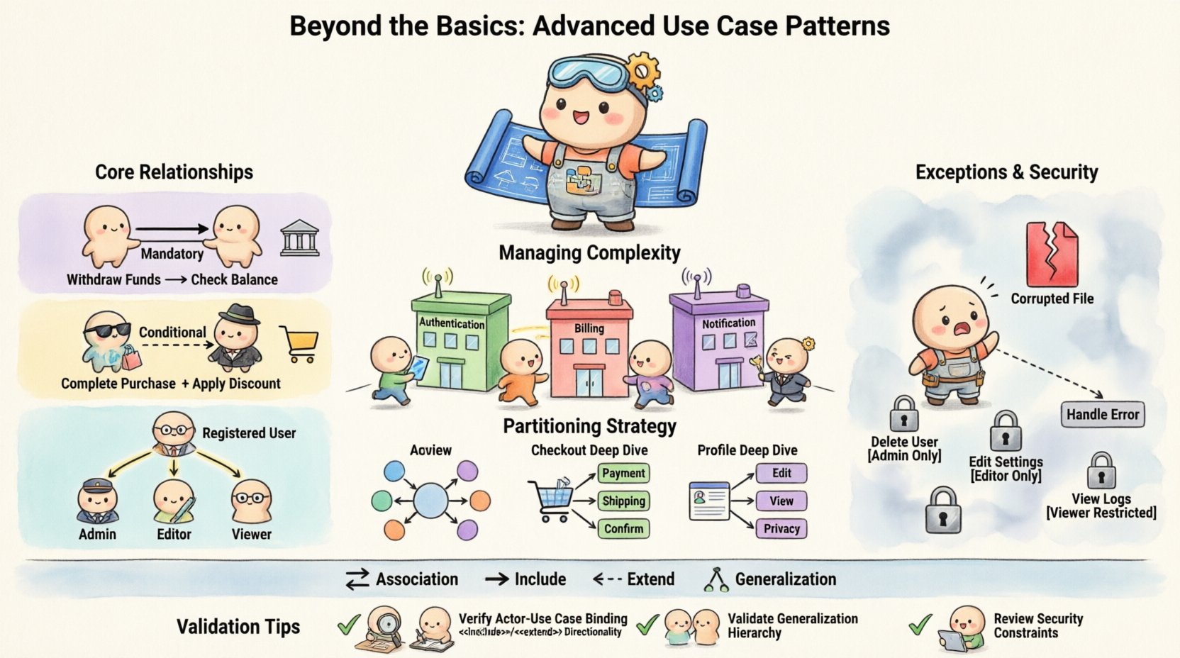
Consider a banking application. The “Withdraw Funds” use case requires a “Check Account Balance” step. Without checking the balance, the withdrawal cannot logically proceed. Therefore, “Check Account Balance” is included within “Withdraw Funds”. This ensures that the system logic remains consistent across all financial transactions.
1.2 The <> Relationship: Optional Variation
In contrast, the <
- Base Use Case remains valid without the extension.
- Extension is triggered by a specific condition (e.g., an error, a timeout, or a specific user choice).
- The extension point is defined in the base use case.
Imagine an online shopping cart. The base use case is “Complete Purchase”. An extension could be “Apply Discount Code”. The purchase can happen without a code, but if a user enters one, the system executes the extension logic. This keeps the primary flow clean while allowing for variations.
It is vital to distinguish between these two. Using <
2. Generalization: Inheritance in Actors and Use Cases 👥
Generalization allows you to create hierarchies. This is powerful for managing complexity when dealing with multiple user types or similar functional blocks.
2.1 Actor Generalization
Actors often share common goals or behaviors. Instead of drawing lines from every specific actor to every shared use case, you can create a parent actor.
- Parent Actor: “Registered User”.
- Child Actors: “Admin”, “Editor”, “Viewer”.
If “Admin” and “Editor” both need access to “Manage Content”, you can define this relationship on “Registered User”. The specific roles inherit this capability. This reduces visual clutter and makes the model easier to maintain. If a new permission is added to “Registered User”, it automatically applies to all children.
2.2 Use Case Generalization
Use cases can also be generalized. This is useful when specific scenarios are variations of a broader action.
- Parent: “Generate Report”.
- Children: “Generate Sales Report”, “Generate Inventory Report”.
The parent defines the common steps (e.g., “Select Date Range”, “Format Data”). The children define the specific filters or output formats. This pattern helps in maintaining a single source of truth for common logic while allowing for specific implementations.
3. Managing Complexity in Large Systems 📊
As systems scale, a single diagram becomes unreadable. Advanced patterns help you partition the model without losing the big picture.
3.1 System Boundaries and Subsystems
Complex applications often consist of multiple subsystems. You can group use cases into subsystems to show which part of the architecture handles specific functionality.
- Authentication Subsystem: Handles all login and password reset flows.
- Billing Subsystem: Handles payment processing and invoicing.
- Notification Subsystem: Handles email and SMS dispatch.
Actors may interact with multiple subsystems. An “Admin” actor might interact with the Authentication subsystem to change passwords and the Billing subsystem to view invoices. Mapping these boundaries clearly prevents developers from placing logic in the wrong module.
3.2 Partitioning by Context
Another strategy is to split diagrams by context. Instead of one massive diagram, create a set of diagrams:
- High-Level Overview: Shows the main actors and top-level use cases.
- Deep Dive 1: Details the “Checkout” flow in isolation.
- Deep Dive 2: Details the “User Profile Management” flow.
This approach ensures that stakeholders can focus on what matters to them without being overwhelmed by irrelevant details.
4. Handling Exceptions and Security Contexts 🔒
Standard use case diagrams often ignore failure states. Advanced modeling incorporates these scenarios explicitly.
4.1 Exception Flows via Extend
Use the <
4.2 Security and Permissions
Use cases can serve as a model for access control. By tagging use cases with security constraints, you create a blueprint for role-based access control (RBAC).
- Tagging: Mark “Delete User” as “Admin Only”.
- Validation: Ensure that the implementation matches the diagram.
This is particularly useful for compliance. In regulated industries, you must prove that only authorized actors can perform specific actions. The diagram provides this audit trail.
5. Comparison of Relationship Types
To clarify the distinctions between the core relationships, refer to the table below.
| Relationship | Direction | Condition | Dependency |
|---|---|---|---|
| Association | Actor ←→ Use Case | Actor initiates | Actor needs to access Use Case |
| Include | Base → Included | Mandatory | Base cannot function without Included |
| Extend | Extension → Base | Optional / Conditional | Extension adds to Base only if triggered |
| Generalization | Child ←→ Parent | Inheritance | Child inherits behavior of Parent |
6. Common Pitfalls and How to Avoid Them ⚠️
Even experienced modelers make mistakes. Here are the most common errors and the strategies to correct them.
- Mixing Control and Flow: Do not include steps like “Click Button” or “Press Enter”. Use Case Diagrams focus on business functionality, not UI details. If you need UI details, use a Sequence Diagram.
- Overusing Include: If a use case is included too many times, it might indicate a need for a separate subsystem or a refactor. High coupling makes the system hard to change.
- Ignoring the Actor: Every line from an actor must lead to a meaningful use case. If an actor connects to a use case that does nothing for them, remove the line.
- Too Many Actors: If you have 50 actors, your diagram is likely too granular. Group them into generalized roles like “External System” or “Internal User”.
7. Validation and Maintenance Strategies ✅
A model is not a one-time task. It evolves as the software evolves. To keep the diagram useful, adopt a maintenance strategy.
- Version Control: Store your diagrams alongside your code. When a feature changes, update the diagram immediately.
- Review Cycles: Include diagram reviews in your sprint planning. Ask: “Does this diagram reflect the current architecture?”
- Traceability: Link use cases to requirements documents. If a requirement is deleted, the corresponding use case should be flagged for review.
8. Advanced Scenario: Multi-Actor Collaboration 🤝
Sometimes, a single use case requires the collaboration of multiple actors. This is common in workflow systems.
8.1 The Approval Workflow
Consider a document approval process. The “Submit Document” use case is initiated by an “Employee”. However, the “Approve Document” use case is initiated by a “Manager”. These are distinct use cases, but they are linked by the state of the document.
To model this effectively:
- Define “Submit Document” as a trigger.
- Define “Approve Document” as the subsequent step.
- Use an <
> relationship if the manager can reject the document, adding a “Notify Employee” extension.
This shows the handoff between roles without cluttering the diagram with internal state transitions.
9. Integrating with Other Diagrams 🧩
Use Case Diagrams do not exist in isolation. They are the entry point for deeper design.
- Class Diagrams: Use cases define the services. Classes define the implementation. The methods in a Class should map to the steps in a Use Case.
- Sequence Diagrams: Use Cases define the *what*. Sequence Diagrams define the *when* and *how* over time. A complex Use Case should have a corresponding Sequence Diagram.
- State Machine Diagrams: If a Use Case involves complex state changes (e.g., Order Status), a State Machine Diagram provides better visibility.
10. Conclusion on Pattern Selection 📝
Selecting the right pattern depends on the system’s complexity. For simple tools, basic associations suffice. For enterprise systems, the depth of Include, Extend, and Generalization is necessary for clarity. The goal is not to make the diagram look complex, but to make the system understandable.
By rigorously applying these advanced patterns, you ensure that the documentation remains a valid asset throughout the software lifecycle. It becomes a tool for communication between stakeholders, developers, and testers, rather than just a static artifact.
Remember, the diagram is a map. If the territory changes, the map must change. Keep your patterns consistent, your relationships logical, and your actors meaningful. This discipline leads to robust software architecture. 🏗️