Unified Modeling Language (UML) serves as a foundational tool for visualizing, specifying, constructing, and documenting the artifacts of software systems. Among the various diagram types available, the Use Case Diagram stands out as a critical instrument for capturing functional requirements. It provides a high-level view of the system by illustrating how users interact with it. This guide explores the essential elements, relationships, and best practices required to construct effective diagrams without relying on specific tools.
When beginning this process, the goal is clarity. Stakeholders, developers, and testers all benefit from a visual representation of system boundaries and interactions. A well-constructed diagram reduces ambiguity and aligns the team on what the system must do. This article covers the anatomy of a Use Case Diagram, the nature of actors, the logic of relationships, and the steps to build these diagrams from the ground up.
Understanding the Purpose of Use Case Diagrams 🧠
Before drawing any shapes, it is crucial to understand the why. A Use Case Diagram is not a flowchart. It does not show the internal logic of a specific feature, such as the exact sequence of buttons clicked. Instead, it focuses on the goals users want to achieve. It answers the question: “What can the system do for the actor?”
Key objectives include:
Requirement Capture: Identifying the functional needs of the system from a user perspective.
Communication: Bridging the gap between technical teams and non-technical stakeholders.
Scope Definition: Clearly delineating what is inside the system and what remains external.
Analysis: Helping developers understand the extent of their work before writing code.
By focusing on goals rather than implementation details, these diagrams remain stable even as the underlying technology changes. This stability makes them valuable assets throughout the software development lifecycle.
Core Components of a Use Case Diagram 🔍
To build a diagram, you must understand the standard notation. Every element serves a specific function in defining the system’s behavior. Below are the primary components used in standard UML notation.
1. Actors 👤
An actor represents a role played by an external entity that interacts with the system. Actors can be human users or other systems. They are typically depicted as stick figures.
Types of Actors:
Primary Actor: The user who initiates the interaction to achieve a specific goal. For example, a “Customer” initiating a purchase.
Secondary Actor: An entity that supports the primary actor or the system. For example, a “Payment Gateway” processing the transaction.
System Actor: Another software system that interacts with the current system.
When defining actors, avoid naming specific individuals. Instead, use roles. “John” is a person; “Administrator” is a role. Roles remain relevant even if the personnel changes.
2. Use Cases 🎯
A use case represents a specific goal or function that the system performs. It is usually drawn as an oval or ellipse. The label inside the oval should describe an action, such as “Place Order” or “Login”.
Best Practices for Use Cases:
Verb-Noun Format: Names should start with a verb (e.g., “Create Report”) to imply action.
Atomic Goals: Each use case should represent one distinct goal. Split complex goals into multiple use cases.
User-Centric: Focus on what the user achieves, not how the system does it.
3. System Boundary 📦
The system boundary is a rectangle that encloses all the use cases. It defines the scope of the system being modeled. Everything inside the box is part of the system; everything outside is external.
Actors are always placed outside the boundary. This visual cue reinforces that actors are external to the system logic they interact with. Lines connecting actors to use cases cross this boundary, symbolizing interaction.
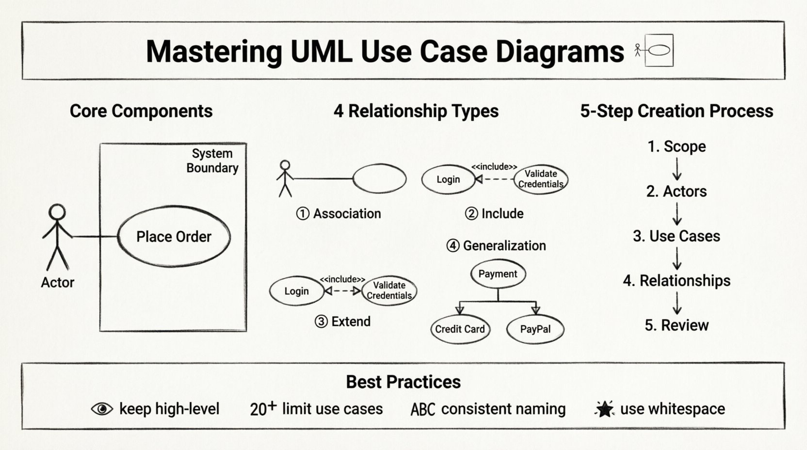
4. Relationships 🔗
Lines connecting elements indicate how they interact. There are four primary relationship types in Use Case Diagrams. Understanding the distinction between them is vital for accuracy.
Relationship Type | Symbol | Meaning |
|---|---|---|
Association | Solid Line | A direct communication path between an actor and a use case. |
Include | Dashed Line <<include>> | The base use case always calls the included use case. It is a mandatory dependency. |
Extend | Dashed Line <<extend>> | The extending use case adds behavior to the base use case only under specific conditions. |
Generalization | Solid Line with Hollow Arrow | Represents an inheritance relationship between actors or use cases. |
Deep Dive into Relationships 🔄
Relationships often confuse beginners. Let us clarify the logic behind them.
Association
This is the simplest link. It shows that an actor can perform a use case. If a “Customer” can “View Product,” there is a solid line connecting them. This is the foundation of the diagram.
Include
Use this when a use case always requires another use case to complete its function. For example, “Place Order” might always require “Confirm Payment”. You can view “Confirm Payment” as a subroutine that is always triggered.
Example Scenario:
Base Use Case: Register User
Included Use Case: Verify Email
Logic: You cannot complete registration without verifying the email.
Extend
This is the opposite of Include. It represents optional behavior. The extending use case only happens if a specific condition is met.
Example Scenario:
Base Use Case: Withdraw Cash
Extending Use Case: Apply Surcharge
Logic: A surcharge only applies if the withdrawal amount exceeds a limit.
Generalization
This indicates that one element is a specialized version of another.
Actor Generalization: A “Manager” is a type of “Employee”. The Manager inherits all capabilities of an Employee but may have additional ones.
Use Case Generalization: “Pay with Card” is a type of “Pay Online”.
Step-by-Step Creation Process 📝
Creating a diagram from scratch requires a structured approach. Do not start drawing immediately. Follow these phases to ensure accuracy.
Phase 1: Identify the System Scope 🌍
Define the boundaries of the system. What is being built? What is the context? Write a brief description of the system’s purpose. This prevents scope creep during the modeling process.
Phase 2: Identify Actors 🧑💼
List all potential users and external systems. Ask questions like:
Who initiates the process?
Who receives the output?
Are there automated systems involved?
Group similar actors together to avoid clutter. If multiple users perform the same tasks, represent them as a single role.
Phase 3: Identify Use Cases 🎯
Brainstorm the goals each actor wants to achieve. Do not think about features yet; think about value. What is the user trying to accomplish?
Technique: For each actor, ask “What can this actor do to get value from this system?”
Phase 4: Map Relationships 🕸️
Draw lines to connect actors to use cases. Determine if relationships are mandatory (Include) or optional (Extend). Ensure every actor has a clear purpose within the system.
Phase 5: Review and Refine 🔍
Walk through the diagram. Is it readable? Are the names clear? Does it accurately reflect the system requirements? Get feedback from stakeholders before finalizing.
Best Practices for Clarity ✨
A diagram that is hard to read is useless. Follow these guidelines to maintain high quality.
Keep it High-Level: Do not include every single button click. Focus on major interactions.
Limit Use Case Count: If a diagram has more than 20 use cases, it may be too complex. Consider breaking it into subsystems.
Consistent Naming: Use standard terminology across the project. Do not mix “Login” and “Sign In” for the same action.
Avoid Overlapping: Ensure use cases do not overlap in meaning. If they do, merge them or clarify the distinction.
Use White Space: Arrange elements to minimize line crossing. A clean layout aids understanding.
Common Pitfalls to Avoid ⚠️
Even experienced modelers make mistakes. Be aware of these common errors.
1. The “Happy Path” Trap
Many diagrams only show the ideal scenario. For example, “Login” might only show success. However, a system also handles failure. While Use Case Diagrams do not show error flows explicitly, the use case name should imply the scope, such as “Manage Account” rather than “Change Password”.
2. Confusing Data with Behavior
A common mistake is modeling data entities as use cases. For example, “Create Customer” is a use case (action). “Customer Data” is not. Use cases must be actions.
3. Overusing Include and Extend
Do not use these relationships for every connection. Use them only when there is a clear logical dependency or optionality. Too many dashed lines make the diagram messy.
4. Ignoring Non-Human Actors
Do not forget external systems. If your application sends data to a CRM, the CRM is an actor. Ignoring these leads to incomplete requirements.
5. Mixing Levels of Abstraction
Do not mix high-level business goals with low-level system functions. “Manage Inventory” is high-level. “Check Stock Quantity” is low-level. Stick to one level per diagram.
Maintaining Diagrams Over Time 🔄
Software evolves. Requirements change. A diagram created at the start of a project may become obsolete if not maintained.
Version Control: Keep track of changes. If a use case is removed, document why.
Regular Reviews: Revisit the diagram during sprint planning or requirement reviews.
Documentation: Link the diagram to detailed requirement documents. The diagram is a summary, not the entire story.
Collaboration and Teamwork 🤝
Use Case Diagrams are not solitary artifacts. They are communication tools.
Workshops: Conduct sessions with stakeholders to validate actors and use cases.
Feedback Loops: Allow developers to review the diagram for technical feasibility.
Shared Understanding: Ensure everyone agrees on the definitions of key terms used in the diagram.
Final Thoughts 🏁
Creating clear Use Case Diagrams is a skill that improves with practice. It requires a balance between technical accuracy and business understanding. By focusing on goals, using standard notation, and avoiding common pitfalls, you can produce diagrams that serve as a reliable blueprint for system development.
Remember that the diagram is a means to an end. Its value lies in the discussions it sparks and the clarity it brings to the project. Keep it simple, keep it accurate, and keep it updated.
With these principles in mind, you are well-equipped to model complex systems effectively. The process is iterative. Start simple, refine as you learn, and always prioritize the needs of the users and the system.