Understanding the architecture of a software system is critical for success. One of the most effective ways to visualize interactions between users and systems is through the use of a Use Case Diagram. These diagrams provide a high-level view of functional requirements, making them indispensable for analysts, developers, and stakeholders. This guide addresses common inquiries, breaking down the complexities into manageable insights.
📊 What is a Use Case Diagram?
A Use Case Diagram is a behavioral diagram within the Unified Modeling Language (UML) family. Its primary purpose is to represent the functional requirements of a system from the perspective of external entities. It maps out the interactions between actors and the system itself.
Unlike code-level specifications, this diagram focuses on what the system does, not how it does it. This distinction is vital for early-stage planning and communication. By defining the boundaries of the system, teams can ensure everyone agrees on the scope before development begins.
- Visual Representation: It uses simple shapes to denote users and actions.
- Requirement Mapping: It connects specific user goals to system features.
- Communication Tool: It bridges the gap between technical and non-technical audiences.
🧩 Key Components of the Diagram
To construct a valid diagram, one must understand its fundamental building blocks. Each element serves a specific purpose in defining the system’s behavior.
1. Actors 🧍
An actor represents a role played by an external entity interacting with the system. It is not necessarily a specific person, but rather a function or a job title.
- Human Actors: Administrators, customers, or managers who interact via the user interface.
- System Actors: External software systems, hardware devices, or other services that communicate via APIs or protocols.
- Internal Actors: Sometimes used to represent sub-systems, though often better modeled as system boundaries.
It is important to remember that actors exist outside the system boundary. They initiate actions but do not reside within the system’s logic.
2. Use Cases ⚡
A use case represents a specific goal or task that an actor wishes to achieve. It is depicted as an oval shape containing the name of the function.
- Granularity: Use cases should be atomic enough to be testable but broad enough to cover a complete goal.
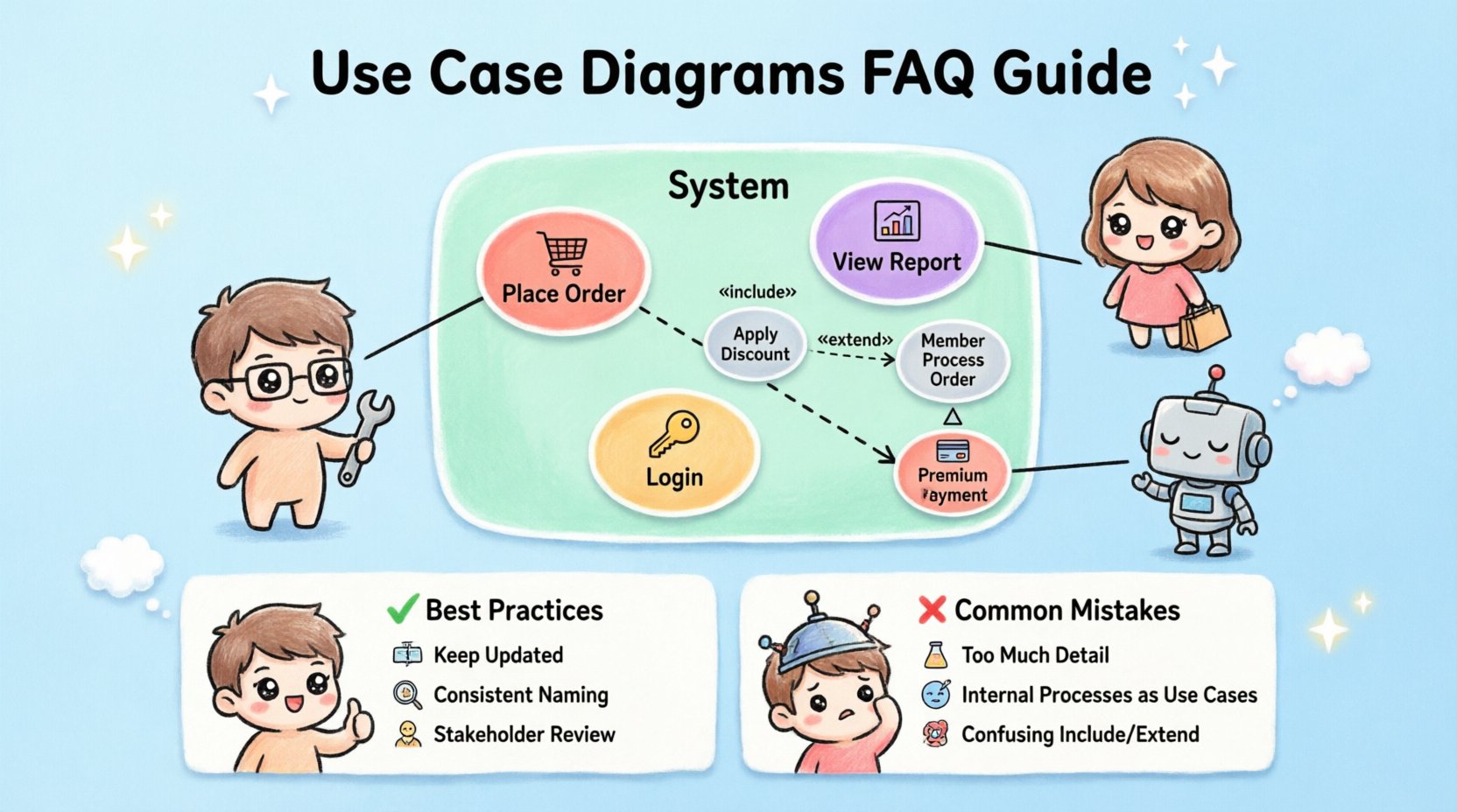
- Naming: They are typically named using a verb-noun structure (e.g., “Place Order,” “View Report”).
- Scope: They define the functionality provided by the system to satisfy the actor’s need.
3. System Boundary 📦
The system boundary is a rectangular box that encloses all use cases. It clearly defines the scope of the project.
- Inside the Box: All internal processes and data handling logic belong here.
- Outside the Box: Actors and external dependencies reside here.
- Crossing the Line: Interactions occur where lines cross the boundary.
4. Associations 🔗
Lines connecting actors to use cases indicate communication. These are standard associations showing that the actor interacts with that specific function.
- Directionality: Usually bidirectional, indicating information flow both ways.
- Labels: Optional labels can describe the type of interaction (e.g., “requests,” “receives”).
🔍 Understanding Relationships
Relationships define how use cases interact with one another. Understanding these is crucial for modeling complex logic without cluttering the diagram.
| Relationship Type | Symbol | Meaning |
|---|---|---|
| Include | Dashed Arrow + «include» | Mandatory behavior inserted into another use case. |
| Extend | Dashed Arrow + «extend» | Optional behavior that activates under specific conditions. |
| Generalization | Solid Arrow + Triangle | Inheritance relationship between actors or use cases. |
Inclusion Relationships 🔄
An include relationship indicates that one use case incorporates the behavior of another. This is mandatory. If the main use case is executed, the included use case must also occur.
- Example: A “Place Order” use case might include “Validate Payment”.
- Benefit: Reduces repetition by defining common steps once.
- Logic: The included use case is a helper function.
Extension Relationships ➕
An extend relationship indicates optional behavior. The base use case can function independently, but the extension activates only if specific conditions are met.
- Example: A “Process Order” use case might be extended by “Apply Discount” if a coupon code is valid.
- Benefit: Keeps the main flow clean while accounting for edge cases.
- Logic: The extension adds functionality without altering the core flow.
Generalization Relationships 📉
Generalization represents inheritance. A specialized actor or use case inherits the properties of a general one.
- Actor Inheritance: A “Premium Member” is a specialized “Member”.
- Use Case Inheritance: A “Print Report” is a specialized “View Report”.
- Benefit: Simplifies diagrams by grouping similar behaviors.
🛠️ How to Create a Use Case Diagram
Creating an accurate diagram requires a structured approach. Follow these steps to ensure clarity and completeness.
Step 1: Identify Actors 🧑💼
List every entity that interacts with the system. Ask yourself: Who uses this? Who maintains it? Who receives output from it?
- Interview stakeholders to find hidden roles.
- Distinguish between primary actors (initiate) and secondary actors (support).
- Ensure every actor has a clear goal.
Step 2: Define Use Cases 🎯
For each actor, list the tasks they perform. Group these tasks logically.
- Focus on user goals rather than system functions.
- Group similar actions into single use cases.
- Avoid listing technical implementation details (e.g., “Click Button X”).
Step 3: Draw the System Boundary 📐
Draw a box around the use cases. Label it with the system name. This visually separates internal logic from external interaction.
Step 4: Connect Actors and Use Cases 🔗
Draw lines between actors and the use cases they initiate. Ensure no actor is isolated and no use case is unreachable.
Step 5: Define Relationships 🧩
Add includes, extends, and generalizations where necessary. Use these to manage complexity and avoid redundancy.
- Use Include for mandatory sub-tasks.
- Use Extend for conditional logic.
- Use Generalization for hierarchical roles.
❌ Common Mistakes to Avoid
Even experienced modelers make errors. Being aware of these pitfalls helps maintain diagram quality.
- Too Much Detail: Do not draw every button click. Keep the view high-level.
- Internal Processes: Do not place internal classes or database tables inside the system boundary as use cases. Use Cases are behaviors, not data structures.
- Missing Actors: Ensure all external dependencies are represented.
- Confusing Includes and Extends: Remember that Include is mandatory, while Extend is optional.
- Flowcharting: Do not use this diagram to show the sequence of steps. That is the job of a Sequence or Activity Diagram.
📋 Comparison with Other Diagrams
Understanding where this diagram fits among others prevents misuse.
| Diagram Type | Primary Focus | Best Used For |
|---|---|---|
| Use Case | Functional Requirements | Defining scope and user goals. |
| Sequence | Interaction Flow | Showing message exchange over time. |
| Class | Data Structure | Modeling objects and relationships. |
| Activity | Workflow | Detailing the steps within a process. |
📝 Frequently Asked Questions
Here are answers to the most common technical questions regarding this modeling technique.
Q: Can an actor be inside the system? 🤔
No. Actors are external by definition. If an entity is inside the system boundary, it is part of the system’s internal logic, not an external actor. Sometimes, a sub-system is treated as an actor if it interacts via an external interface, but technically it is an external dependency.
Q: How many use cases should a diagram have? 📏
There is no fixed number. A diagram should be readable. If it becomes too crowded, consider splitting the diagram by subsystem or grouping actors. A good rule of thumb is to fit the primary interactions on a single page without scrolling.
Q: Do use cases cover non-functional requirements? 🛡️
Generally, no. Use Case Diagrams focus on functional requirements (what the system does). Non-functional requirements (performance, security, reliability) are usually documented in a separate requirements specification or noted as constraints on specific use cases.
Q: Is a Use Case Diagram the same as a Flowchart? 🔄
No. A flowchart shows the logical flow of steps within a process. A Use Case Diagram shows the interactions between users and the system. Do not use a Use Case Diagram to map decision logic or branching paths.
Q: How do I handle complex authentication? 🔐
Authentication is typically an Include relationship. A “Login” use case might include “Verify Credentials”. Alternatively, if authentication is a prerequisite for many functions, you can treat it as a separate use case that is included by all protected functions.
Q: Can I use this for legacy systems? 🏛️
Yes. Use Case Diagrams are excellent for reverse engineering existing systems. By interviewing users and observing the system, you can map the current functionality without needing access to the source code.
Q: What if a use case is too large? 🐘
Break it down. If a use case takes too long to complete or involves too many distinct steps, split it into smaller, more focused use cases. For example, “Manage Inventory” could be split into “Add Item”, “Remove Item”, and “Update Stock”.
Q: Do I need to show data flow? 💾
No. This diagram does not show data flow. It shows interaction. Data flow is better represented in a Data Flow Diagram or detailed within the use case description text.
✅ Best Practices for Documentation
To ensure the diagram remains a useful asset throughout the project lifecycle, adhere to these guidelines.
- Keep it Updated: As requirements change, update the diagram immediately. An outdated diagram is misleading.
- Use Consistent Naming: Adopt a naming convention for actors and use cases across the entire documentation set.
- Write Descriptions: The diagram is a map, not the territory. Write detailed textual descriptions for each use case to capture business logic, preconditions, and postconditions.
- Review with Stakeholders: Walk through the diagram with business owners. Ensure it matches their mental model of the system.
- Version Control: Store the diagram in a version control system to track changes over time.
🚀 Final Considerations
Modeling a system requires precision and foresight. A well-crafted Use Case Diagram serves as a contract between the development team and the business. It clarifies expectations and reduces the risk of scope creep.
By focusing on actors and their goals, you create a user-centric view of the software. This perspective ensures that the final product delivers value to the intended audience. Remember that the diagram is a living document. It evolves as the project evolves.
Invest time in getting the structure right. The effort spent defining these interactions early pays dividends during the implementation and testing phases. Clear communication leads to better software.
Utilize these diagrams to align teams, manage expectations, and document the core functionality of your application. With a solid understanding of components and relationships, you can build robust systems that meet real-world needs.