Creating effective diagrams is a fundamental skill in systems analysis. A Use Case Diagram serves as a visual representation of how users interact with a system. It captures functional requirements and defines the scope of software development. However, a diagram that is difficult to read fails to communicate its intended message. Clarity in modeling ensures that stakeholders, developers, and testers share a unified understanding of the system behavior.
This guide provides actionable strategies for building diagrams that are easy to understand and simple to update over time. We will explore the core components, structural best practices, and maintenance workflows required for high-quality modeling.
Understanding the Purpose of Use Case Diagrams 📋
Before diving into design techniques, it is essential to understand why these diagrams exist. They are not meant to show internal logic or data structures. Instead, they focus on interactions. They answer the question: “Who does what with the system?”.
- Communication Tool: They bridge the gap between technical teams and business stakeholders.
- Scope Definition: They clearly delineate what is inside the system boundary and what is outside.
- Requirement Verification: They help verify that all identified user goals are addressed by the system.
When a diagram is readable, it reduces ambiguity. When it is maintainable, it survives changes in requirements without requiring a complete rewrite.
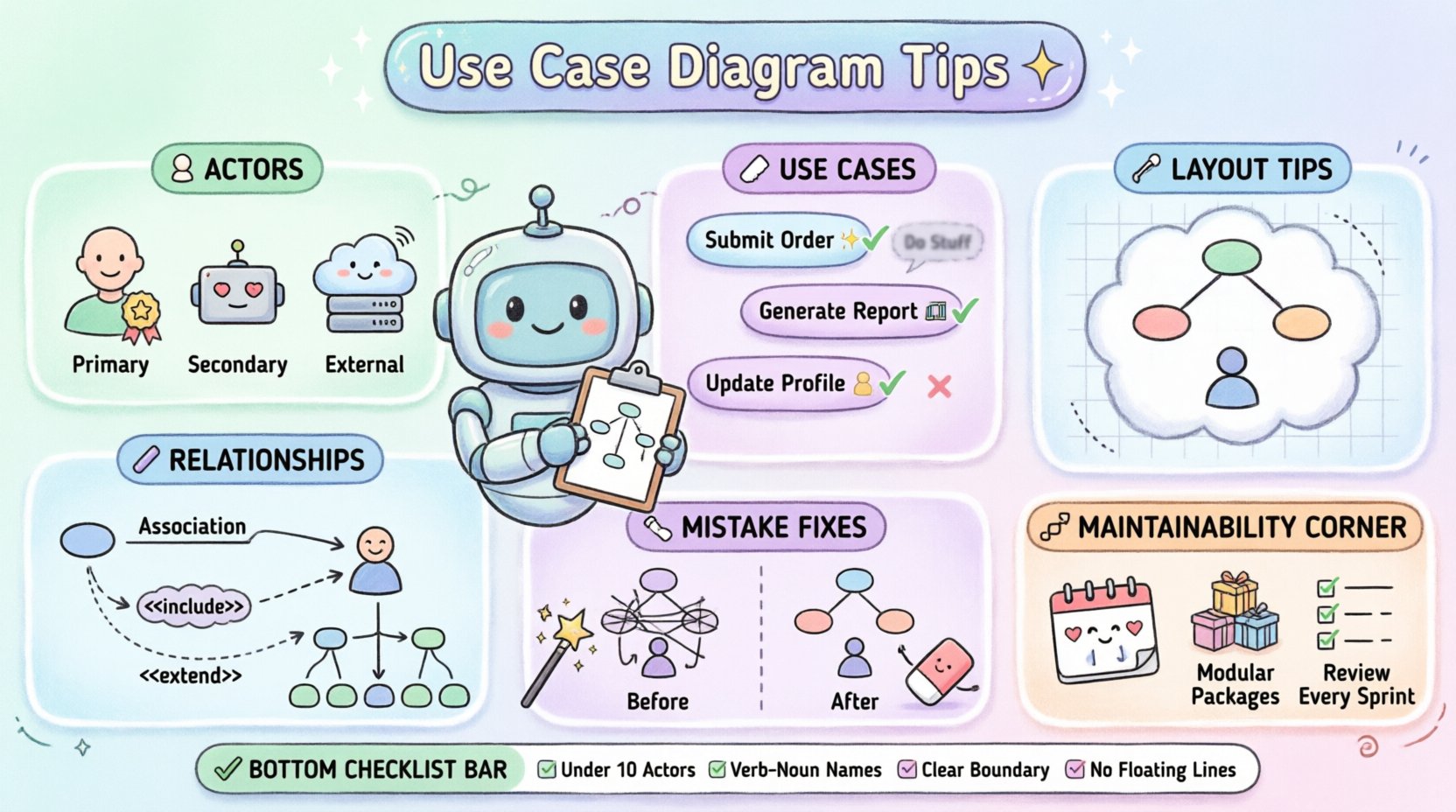
Defining Actors with Precision 👥
Actors represent the external entities that interact with the system. They can be human users, other systems, or hardware components. Identifying the correct actors is the first step toward a clean diagram.
Identifying Primary vs. Secondary Actors
Distinguishing between actors who initiate actions and those who respond is critical.
- Primary Actors: These are the users who actively start a use case to achieve a specific goal. For example, a “Customer” initiating a “Place Order” action.
- Secondary Actors: These systems or users support the primary actor but do not initiate the flow. They often provide data or perform background tasks.
Internal vs. External Actors
Not all actors are people. Sometimes, a legacy system or an email server acts as an actor. To keep the diagram readable:
- Group similar actors together visually.
- Use clear labels that describe the role, not the specific person’s name.
- Avoid creating an actor for every single user; use generalized roles like “Administrator” or “Manager”.
Structuring Use Cases Effectively 🏷️
A use case represents a specific goal or function that the system performs. The way these are named and grouped dictates the diagram’s clarity.
Naming Conventions
Use case names should follow a consistent verb-noun pattern. This makes the diagram read like a list of actions.
- ✅ Good: “Submit Invoice”, “Generate Report”, “Update Profile”.
- ❌ Poor: “Invoice”, “Report”, “Profile”.
Consistent naming helps readers scan the diagram quickly. It also aids in generating documentation later, as the names often become the section headers in functional specifications.
Granularity and Scope
One of the most common errors is creating use cases that are too broad or too narrow.
- Too Broad: “Manage System” covers too many functions and obscures specific behaviors.
- Too Narrow: “Click Button A” is too technical and describes implementation rather than user goals.
- Just Right: “Save Settings” captures a specific user goal without revealing UI details.
A good rule of thumb is that a use case should be completable in one session by one actor without interruption.
Managing Relationships and Connections 🔗
Relationships define how use cases and actors interact. Using them correctly prevents clutter and logic errors.
The Association Line
This is the standard line connecting an actor to a use case. It indicates participation. Keep these lines straight where possible. Avoid crossing lines excessively, as this creates visual noise.
Include vs. Extend
Understanding the semantic difference between <<include>> and <<extend>> is vital for logical correctness.
- Include: Indicates that a use case always incorporates the behavior of another. It is a mandatory dependency. For example, “Place Order” always includes “Validate Payment”.
- Extend: Indicates optional behavior that happens under specific conditions. For example, “Place Order” may extend to “Apply Discount” if a coupon code is entered.
Generalization
Use generalization to show inheritance between actors or use cases. If a “Gold Customer” is a type of “Customer”, draw a generalization line. This reduces redundancy by allowing specific actors to inherit relationships from the parent actor.
Visual Layout and Organization 📐
A well-organized diagram is easier to parse. Visual hierarchy guides the eye to the most important information first.
System Boundaries
Draw a clear rectangle to represent the system under development. Everything inside belongs to the system; everything outside is the environment. Ensure the boundary is large enough to accommodate future growth but small enough to show context.
Alignment and Spacing
Consistency in spacing reduces cognitive load. Use a grid or alignment tools to ensure actors and use cases are evenly distributed.
- Align actors vertically or horizontally.
- Group related use cases together.
- Leave whitespace between distinct functional areas.
Labeling Lines
Not all lines need labels, but associations with conditions should be noted. For example, label a line “if logged in” where an actor connects to a restricted use case.
Common Mistakes and Corrections 🛠️
Avoiding pitfalls is often more important than adding features. The table below highlights frequent errors and how to resolve them.
| Mistake | Impact | Correction |
|---|---|---|
| Crossing Lines | Visual confusion | Rearrange elements to minimize intersections. |
| Actor inside Boundary | Logical error | Move actors outside the system rectangle. |
| Too Many Actors | Cluttered diagram | Consolidate similar roles into a single generic actor. |
| Vague Use Case Names | Ambiguous requirements | Refine names to follow the Verb-Noun pattern. |
| Overuse of Include | Fragmented logic | Use Include only for mandatory steps; move optional steps to Extend. |
| Missing System Boundary | Unclear scope | Always define the system edge clearly. |
Ensuring Maintainability Over Time 🔄
Software evolves. Requirements change. A diagram that cannot be updated becomes obsolete quickly. Maintainability relies on structure and documentation.
Modular Design
Large systems should not have a single massive diagram. Break the system down into subsystems. Create separate diagrams for different modules, such as “User Management” or “Billing”. This keeps individual diagrams manageable.
Version Control
Just like source code, diagrams should be versioned. Record changes in a changelog. Note what was added, removed, or modified in each iteration. This history helps new team members understand the evolution of the system.
Documentation Links
A diagram is a high-level view. It should link to detailed specifications. Use notes or external references to point to user stories, flowcharts, or data models. This keeps the diagram clean while retaining depth.
Regular Reviews
Schedule periodic reviews of the diagrams with stakeholders. Ask specific questions:
- Does this diagram still reflect the current requirements?
- Are there any new actors that have emerged?
- Are any use cases no longer relevant?
Best Practices Checklist ✅
Before finalizing a diagram, run through this checklist to ensure quality.
- Actor Count: Are there fewer than 10 actors on the main diagram?
- Use Case Count: Is the number of use cases manageable (typically under 20 per diagram)?
- Naming: Do all use cases start with a verb?
- Boundary: Is the system boundary clearly defined?
- Connectivity: Are all lines connected to valid endpoints (no floating lines)?
- Clarity: Can a non-technical stakeholder understand the goal of each use case?
- Consistency: Are relationship types (Include/Extend) used correctly?
Advanced Techniques for Complex Systems 🚀
When dealing with enterprise-level systems, standard diagrams may not suffice. Advanced techniques help manage complexity without sacrificing readability.
Use Case Packages
Group related use cases into packages. This acts as a folder structure for the diagram. It allows you to show a high-level view with packages and drill down into specific packages for details.
Abstract Use Cases
Some behaviors are common across multiple use cases. You can define an abstract use case to represent common logic. While not always rendered in every tool, conceptually, this reduces duplication in the design phase.
Context Diagrams
For very large systems, create a context diagram first. This shows the system as a single black box and the actors surrounding it. Then, create detailed diagrams for each actor’s interaction. This hierarchical approach prevents overwhelming the reader.
Integrating with Other Modeling Artifacts 📊
Use Case Diagrams rarely stand alone. They are part of a larger modeling ecosystem. Understanding how they fit helps in creating a cohesive documentation set.
- Sequence Diagrams: Use these to detail the step-by-step interaction flow for a specific use case.
- Activity Diagrams: Use these to show the internal workflow or decision logic within a use case.
- Class Diagrams: Use these to define the data structures required to support the use cases.
Ensuring consistency across these artifacts is key. If a use case is renamed, all linked diagrams must be updated. This synchronization prevents technical debt.
Conclusion on Readability and Structure 🏁
Building a Use Case Diagram is an exercise in abstraction. The goal is to simplify complexity, not hide it. By focusing on clear actor definitions, precise naming, and logical relationships, you create a diagram that serves as a reliable contract between business needs and technical implementation.
Maintainability is just as important as initial design. Treat the diagram as a living document that evolves with the software. Regular reviews and strict adherence to visual standards ensure that the diagram remains a useful asset throughout the project lifecycle.
Remember that the best diagram is the one that is understood by everyone involved. Prioritize clarity over technical completeness. If a stakeholder looks at the diagram and understands the scope, the modeling effort has been successful.
Apply these tips consistently. Over time, the quality of your diagrams will improve, leading to better communication and fewer misunderstandings during development.