Designing software architecture requires a clear vision of how components interact. A UML package diagram serves as the blueprint for organizing these components into manageable units. This guide provides a structured approach to establishing a clean, maintainable package diagram. We will explore the foundational concepts, setup procedures, and strategic best practices. By following this methodology, you ensure your system design remains coherent as the project evolves.
📐 Understanding the UML Package Diagram
A package diagram is a structural diagram used in Unified Modeling Language (UML). Its primary function is to show the organization of packages. In this context, a package acts as a namespace that groups related elements. These elements might include classes, use cases, or other packages. The diagram visualizes the relationships between these groups, such as dependencies and interfaces.
Why is this important? Software systems can become complex quickly. Without a logical structure, code becomes a tangled web of dependencies. A package diagram helps you:
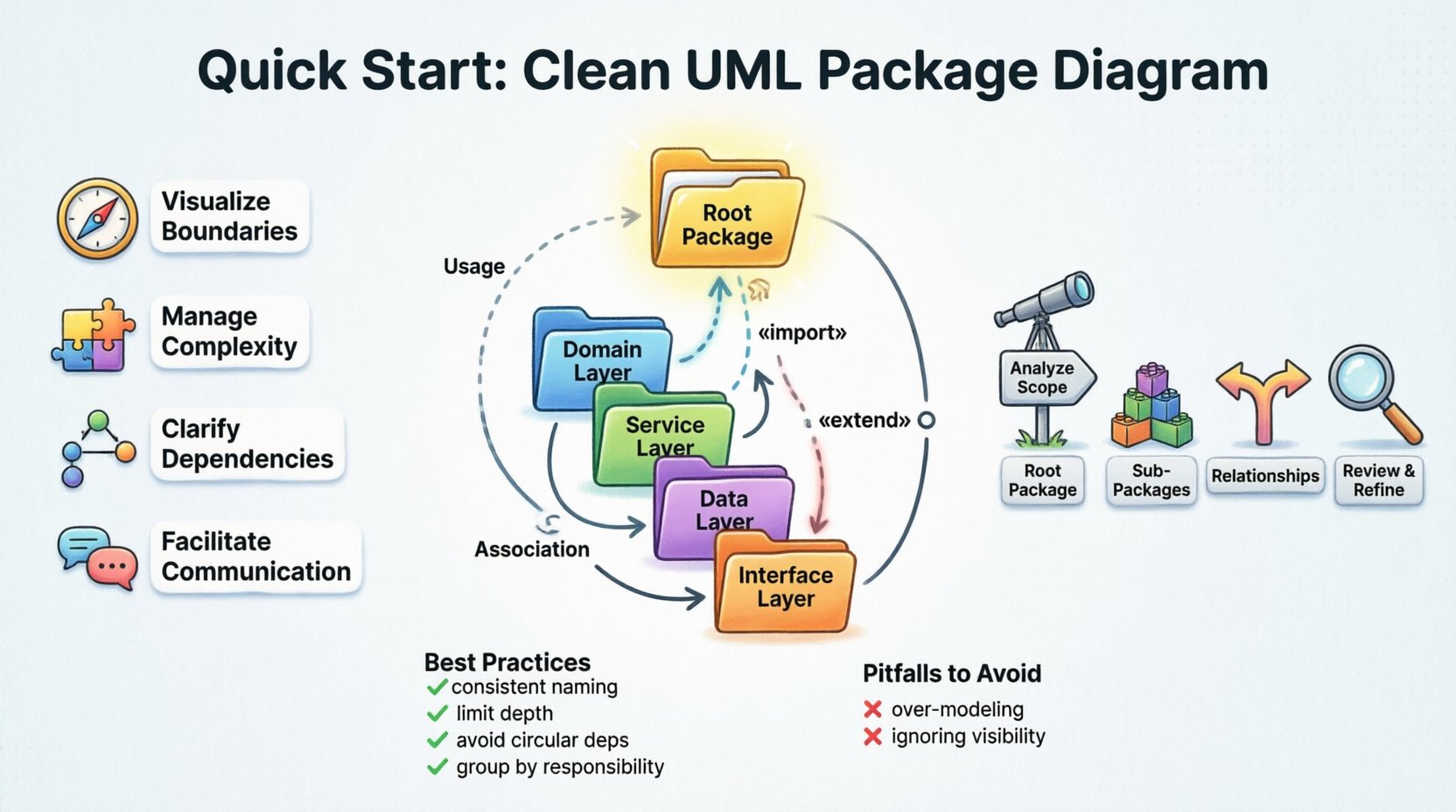
- Visualize Boundaries: Define where one module ends and another begins.
- Manage Complexity: Hide implementation details within packages to reduce cognitive load.
- Clarify Dependencies: Explicitly show how packages rely on one another.
- Facilitate Communication: Provide a common language for developers and stakeholders.
🧱 Core Concepts Before You Begin
Before drawing any lines or boxes, you must understand the building blocks. A clean diagram relies on clear definitions.
1. Packages and Namespaces
A package is not a physical file. It is a logical container. It allows you to group classifiers (classes, interfaces) that share a common purpose. Think of it as a folder in a file system, but with strict rules about visibility and interaction.
2. Dependencies
Dependencies indicate that one package requires another to function. If a class in Package A uses a class in Package B, a dependency exists. These relationships dictate the flow of information and control.
3. Interfaces
Interfaces define a contract. They specify what a package offers to others without revealing how it works. This separation allows packages to change internally without breaking external connections.
4. Visibility
Not everything inside a package is public. You must define what is accessible to other packages. This control prevents tight coupling and ensures stability.
🛠 Step-by-Step Setup Guide
Setting up a diagram requires a methodical approach. Follow these logical steps to construct a robust architecture model.
Step 1: Analyze the System Scope
Start by understanding the boundaries of the application. What are the core features? What external systems does it interact with? Do not start with classes. Start with high-level capabilities.
- Identify major functional areas.
- Define the entry points for the system.
- List external dependencies (databases, APIs, legacy systems).
Step 2: Define the Root Package
Create a single root package representing the entire system. This acts as the container for all other elements. It should have a clear, descriptive name.
- Use a standard naming convention.
- Ensure this package does not contain logic, only structure.
- Mark it as the top level of your hierarchy.
Step 3: Create Sub-Packages
Divide the root package into logical sub-packages. Group related functionality together. Avoid creating too many small packages, as this creates visual noise. Aim for cohesion within packages and low coupling between them.
- Domain Layer: Contains business rules and entities.
- Service Layer: Handles business logic and orchestration.
- Data Layer: Manages storage and retrieval.
- Interface Layer: Defines external APIs and user interfaces.
Step 4: Establish Relationships
Draw lines between packages to show how they interact. Use the correct symbol for the relationship type. This step is critical for understanding data flow.
- Use solid arrows for dependencies.
- Use dashed lines for realization or usage.
- Ensure arrows point from the dependent package to the provider.
Step 5: Review and Refine
Once the initial draft is complete, review it against your design principles. Check for circular dependencies and overly complex paths. Simplify where possible.
📊 Understanding Dependency Types
Different types of relationships convey different levels of commitment. Using the correct notation prevents ambiguity.
| Dependency Type | Symbol | Description | Usage Scenario |
|---|---|---|---|
| Usage | Dashed Line + Open Arrow | One package uses the interface of another. | Calling a method in another package. |
| Import | Dashed Line + «import» | One package imports all elements of another. | Accessing public types directly. |
| Extension | Open Arrow + «extend» | One package extends the behavior of another. | Inheritance or interface implementation. |
| Association | Solid Line | A structural relationship between packages. | Long-term structural link. |
🎨 Best Practices for Clean Diagrams
A clean diagram is easy to read and update. Follow these guidelines to maintain quality over time.
1. Consistent Naming Conventions
Names should be descriptive and consistent. Avoid abbreviations unless they are standard industry terms. Use a standard casing style (e.g., PascalCase or camelCase) for all packages.
- Good:
PaymentProcessing - Bad:
PPorPayment
2. Limit Package Depth
Deep hierarchies are hard to navigate. Try to keep the structure flat. If you find yourself needing more than three levels of nesting, reconsider your grouping strategy.
3. Avoid Circular Dependencies
Circular dependencies occur when Package A depends on Package B, and Package B depends on Package A. This creates a loop that makes maintenance difficult and testing complex.
- Identify loops during the design phase.
- Introduce an interface or abstraction to break the cycle.
- Ensure dependencies flow in one direction (e.g., from UI to Service to Data).
4. Group by Responsibility
Apply the Single Responsibility Principle to packages. A package should have one reason to change. If a package handles both database access and user interface logic, split it.
5. Use Stereotypes Sparingly
Stereotypes add metadata to elements. Use them to clarify intent, such as «entity» or «controller». Do not overuse them, or the diagram becomes cluttered.
🚧 Common Pitfalls to Avoid
Even experienced architects make mistakes. Recognizing these pitfalls helps you avoid them.
- Over-Modeling: Trying to capture every detail in the diagram. Focus on the high-level structure, not every class.
- Ignoring Visibility: Treating all elements as public. Define visibility to control access.
- Naming Conflicts: Using the same name for different packages in different contexts.
- Static Diagrams: Creating a diagram that is never updated. The model must evolve with the code.
🔄 Maintenance and Evolution
A package diagram is a living document. As the project grows, the diagram must grow with it. Regular reviews ensure the model remains accurate.
1. Schedule Regular Reviews
Set a recurring time to review the architecture. Check if new packages align with the existing structure. Update relationships as features are added.
2. Version Control the Model
Store the diagram definition in your version control system. This allows you to track changes over time and revert if necessary.
3. Align with Code
The diagram should reflect the actual codebase. If you refactor the code, update the diagram immediately. Discrepancies between the model and the code lead to confusion.
4. Automate Where Possible
Many tools can generate diagrams from source code. Use these features to keep the diagram synchronized with the implementation. This reduces the manual effort required for updates.
🔍 Analyzing Package Coupling
Coupling measures how tightly connected two packages are. High coupling makes systems rigid. Low coupling makes them flexible.
- Low Coupling: Packages interact through well-defined interfaces. Changes in one package have minimal impact on others.
- High Coupling: Packages rely on internal details of others. This makes refactoring difficult and risky.
When setting up your diagram, aim for low coupling. Use dependency injection principles where applicable. This ensures that dependencies are managed externally rather than internally.
🏗 Layered Architecture Considerations
Many projects use a layered architecture. This structure imposes specific rules on package dependencies.
- Presentation Layer: Depends on the Application Layer.
- Application Layer: Depends on the Domain Layer.
- Domain Layer: Should have no dependencies on other layers.
- Infrastructure Layer: Provides implementations for Domain abstractions.
Ensure your package diagram reflects this flow. Arrows should generally point downwards. Upward dependencies indicate a violation of architectural rules.
📝 Summary of Key Actions
To summarize the setup process:
- Define the root package clearly.
- Group related elements into logical sub-packages.
- Use standard dependency symbols.
- Enforce naming conventions.
- Avoid circular dependencies.
- Maintain the diagram alongside the code.
By adhering to these principles, you create a foundation that supports long-term development. A clean package diagram is not just a drawing; it is a strategic tool for managing complexity. It guides the development team and ensures the system remains scalable. Take the time to get the structure right early, and you will save significant effort during the implementation phase.
Remember, the goal is clarity. If someone else can read your diagram and understand the system structure without asking questions, you have succeeded. Keep the design simple, the dependencies explicit, and the documentation current.