Information Systems students often encounter a pivotal moment in their academic journey. This is the point where abstract requirements transform into concrete visual models. Among the various tools available in the Unified Modeling Language (UML), the Use Case Diagram stands out as a fundamental instrument. It bridges the gap between stakeholders and technical teams. Understanding this diagram is not just about drawing lines and circles. It is about defining the scope of a system and clarifying how users interact with it. 🎯
This guide provides a deep dive into the mechanics, purpose, and application of Use Case Diagrams. We will explore the core components, relationships, and best practices without relying on specific software tools. The focus remains on the conceptual framework that drives successful system analysis and design.
Understanding the Purpose of Use Case Diagrams 📐
Before drawing a single line, it is essential to understand why this artifact exists. In the context of Information Systems, clarity is currency. Stakeholders often struggle to articulate what they need in technical terms. Developers, conversely, often struggle to understand the business context behind a feature. A Use Case Diagram serves as a communication bridge.
Its primary objectives include:
- Visualizing Functional Requirements: It translates a list of features into a graphical format that is easier to digest.
- Defining System Boundaries: It clearly distinguishes between what is inside the system and what is outside.
- Identifying Actors: It reveals who or what interacts with the system, whether human or external software.
- Facilitating Collaboration: It allows business analysts and developers to agree on the system’s scope before writing code.
When students master this notation, they gain the ability to analyze complex systems. They learn to separate the “what” from the “how”. This separation is critical in systems engineering. It ensures that the architecture supports the requirements without getting bogged down in implementation details.
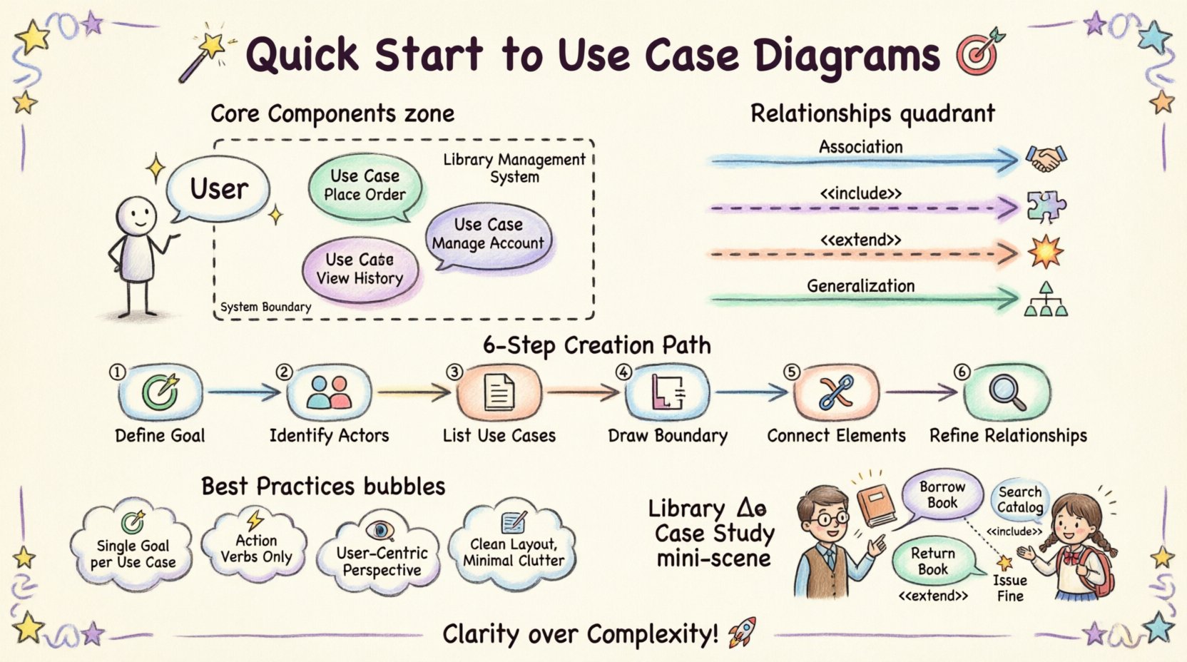
Core Components of a Use Case Diagram 🧩
A Use Case Diagram is composed of specific elements. Each element carries a distinct meaning. Understanding these building blocks is the foundation of creating accurate diagrams. There are three main components: Actors, Use Cases, and the System Boundary.
1. Actors 👤
An Actor represents an external entity that interacts with the system. It is important to note that an Actor is not necessarily a person. It can be a role, a department, or even another system. Actors are typically depicted as stick figures or icons.
Key characteristics of Actors include:
- External to the System: Actors exist outside the boundary of the software being modeled.
- Goal-Oriented: Actors initiate interactions to achieve a specific goal.
- Roles, Not Individuals: A diagram should model roles like “Customer” or “Admin”, not specific names like “John Smith”.
2. Use Cases 🔄
A Use Case represents a specific function or interaction within the system. It is the “what” that the system does. Use Cases are usually drawn as ovals or ellipses placed inside the system boundary.
When defining a Use Case, consider the following:
- Single Goal: Each Use Case should address one specific goal for the actor.
- Verb-Noun Naming: Names should be clear, such as “Place Order” or “Generate Report”.
- System Internal: The logic and processing happen within the boundary of the system.
3. System Boundary 📦
The System Boundary is a rectangle that encloses all the Use Cases. It defines the scope of the project. Anything outside the rectangle is part of the environment. Anything inside is part of the system.
This boundary helps in managing complexity. It prevents the diagram from becoming cluttered with external processes. It serves as a clear visual delimiter for the scope of work.
Relationships Between Elements 🔗
The lines connecting Actors, Use Cases, and other Use Cases represent relationships. These lines dictate the flow and dependency of interactions. There are four primary relationship types that define the behavior of the system.
| Relationship | Description | Symbol |
|---|---|---|
| Association | A communication link between an Actor and a Use Case. | Simple Line |
| Include | A mandatory dependency where one Use Case includes the behavior of another. | Dashed Arrow + <<include>> |
| Extend | An optional dependency where behavior is added under specific conditions. | Dashed Arrow + <<extend>> |
| Generalization | Inheritance where a child Actor or Use Case inherits from a parent. | Solid Triangle Arrow |
Association
This is the most common relationship. It shows that an Actor can initiate a specific Use Case. The direction of the association usually indicates who initiates the interaction. For example, a “Customer” initiates the “Place Order” Use Case.
Include Relationship
An Include relationship indicates that a Use Case incorporates the behavior of another Use Case. This is used to reduce redundancy. If multiple Use Cases require the same step, that step can be extracted into a separate Use Case and included.
For instance, both “Place Order” and “Return Item” might require “Verify Authentication”. Instead of drawing the authentication steps twice, you define it once and include it.
Extend Relationship
An Extend relationship represents optional behavior. It adds functionality to a base Use Case only under specific conditions. This is useful for error handling or rare events.
Consider a “Print Receipt” Use Case. It might be extended by “Email Receipt” only if the customer opts for digital delivery. The base flow remains intact, but the extension adds value conditionally.
Generalization
Generalization allows for inheritance. In the context of Actors, a specialized Actor inherits the capabilities of a generalized Actor. For example, a “Manager” is a type of “Employee”. The Manager can do everything an Employee can do, plus specific management tasks.
In Use Cases, a specialized Use Case can extend a general one. This is less common but useful when breaking down complex actions into sub-actions.
Steps to Create a Use Case Diagram 🛠️
Creating a diagram is a structured process. It requires analysis before visualization. Follow these steps to ensure accuracy and completeness.
Step 1: Identify the System Goal 🎯
Start by defining the primary purpose of the system. What problem does it solve? This high-level view sets the context for the entire diagram. Without a clear goal, the diagram lacks focus.
Step 2: Identify the Actors 👥
Who interacts with this system? Brainstorm all potential users and external systems. Ask questions like:
- Who initiates the main processes?
- Who receives output from the system?
- Are there automated systems that feed data into this one?
List every role identified. Do not worry about grouping them yet. Capture the full scope of interaction.
Step 3: Define the Use Cases 📝
For each Actor, determine what they want to achieve. These goals become the Use Cases. Ensure each Use Case represents a complete unit of functionality. Avoid breaking a single goal into too many small steps at this stage.
Step 4: Draw the System Boundary 📏
Draw a rectangle. Place the Use Cases inside it. Place the Actors outside it. This visual separation is crucial for maintaining the correct perspective.
Step 5: Connect Actors to Use Cases 🔗
Draw lines between Actors and the Use Cases they interact with. Ensure the lines are clear and do not cross unnecessarily. Label the lines if necessary to clarify the direction of initiation.
Step 6: Refine Relationships 🔍
Review the diagram for redundancies. Identify common behaviors that can be extracted into Include relationships. Look for optional behaviors that fit Extend relationships. Check for generalization opportunities among Actors.
Best Practices for Information Systems Students 📚
Writing a diagram is different from drawing one. There are conventions and best practices that enhance readability and utility. Adhering to these standards ensures that the diagram serves its purpose effectively.
1. Maintain a Single Goal per Use Case
A Use Case should represent one distinct interaction. If a Use Case tries to do too much, it becomes difficult to manage. Break complex actions into smaller, manageable Use Cases. This granularity helps in testing and validation later.
2. Use Action-Oriented Names
Names should be clear and descriptive. Use the format “Verb + Noun”. For example, use “Search Product” instead of “Search”. Use “Update Profile” instead of “Edit”. This ensures that the function is understood without further explanation.
3. Avoid Internal Details
A Use Case Diagram is a high-level view. Do not include database operations, specific screen layouts, or code logic inside the diagram. Keep the focus on the interaction between the user and the system. Detailed logic belongs in Use Case Descriptions or Sequence Diagrams.
4. Focus on the User’s Perspective
The diagram should answer the question: “What can the user do with this system?”. Avoid modeling internal system processes unless they are directly visible or initiated by an Actor. The boundary should be defined by the user’s interaction points.
5. Keep It Clean
A cluttered diagram is a useless diagram. Avoid lines crossing over each other. Arrange Actors and Use Cases logically. Group related Use Cases together. Use whitespace effectively to improve readability.
Common Mistakes to Avoid ⚠️
Students often fall into traps when creating their first diagrams. Being aware of these common errors can save time and prevent confusion.
- Mixing Data Flow with Use Cases: A Use Case is not a data flow. It is a functional goal. Do not model data moving between systems as Use Cases unless a user initiates that transfer.
- Too Many Use Cases: If a single Use Case has hundreds of steps, it is likely too large. Refine it into smaller, more specific Use Cases.
- Ignoring Non-Human Actors: Remember that external systems can be Actors. If the system receives data from a sensor or another API, that external entity should be modeled as an Actor.
- Overusing Include/Extend: Do not force relationships where they do not fit. If a step is always required, use Include. If it is optional, use Extend. Do not use them for simple control flow.
- Confusing Generalization: Do not confuse “is a” with “uses”. A “Manager” is an “Employee” (Generalization). A “Manager” uses “Approve Loan” (Association).
Integration with Other Documentation 📄
A Use Case Diagram does not exist in isolation. It is part of a larger documentation suite. It works in tandem with textual descriptions and other diagrams to provide a complete picture of the system.
Use Case Descriptions
For every Use Case on the diagram, there should be a corresponding text description. This document details the flow of events. It covers the main success scenario, alternative flows, and preconditions. The diagram provides the overview; the description provides the detail.
Sequence Diagrams
Once the Use Cases are defined, Sequence Diagrams can be used to map the interactions over time. They show the order of messages between objects. The Use Case Diagram identifies the “what”, while the Sequence Diagram helps define the “how”.
Entity Relationship Diagrams
Use Cases often require data. An Entity Relationship Diagram models the data structures. The Use Case Diagram tells you which data is accessed, and the ER Diagram tells you how that data is stored.
The Role of Tools in the Process 🖥️
While this guide avoids specific software names, it is important to acknowledge the role of tools in the creation process. Professional analysts use diagramming applications to create these models. These tools assist in maintaining consistency and generating documentation.
When selecting a tool, consider the following criteria:
- Standard Compliance: Ensure the tool supports standard UML notation.
- Collaboration: Can multiple people work on the diagram simultaneously?
- Export Options: Can the diagram be exported to images or PDF for reporting?
- Modeling Capabilities: Does it support linking to textual descriptions?
The tool is merely a medium. The value lies in the analysis performed by the student. The diagram is a thinking tool, not just a drawing.
Case Study Example: Library Management System 📚
To illustrate these concepts, consider a Library Management System. This example demonstrates how to apply the principles discussed.
Actors
- Librarian: Manages the books and members.
- Member: Borrows and returns books.
- System: Automated notifications.
Use Cases
- Register Member: New members sign up.
- Borrow Book: Member takes a book home.
- Return Book: Member gives a book back.
- Search Catalog: Member looks for a book.
- Issue Fine: System calculates overdue penalties.
Relationships
- Librarian is associated with Register Member.
- Member is associated with Borrow Book.
- Borrow Book includes Search Catalog (you must find the book before borrowing).
- Return Book extends Issue Fine (fine is only issued if overdue).
This structure ensures that the scope is clear. Everyone understands who does what. The boundary separates the library software from the members and the librarian.
Advanced Considerations for Complex Systems 🔬
As systems grow in complexity, so does the diagram. Large Information Systems may require multiple Use Case Diagrams. This is known as partitioning.
Package Diagrams
When a system has hundreds of Use Cases, a single diagram becomes unreadable. You can group Use Cases into packages. These packages can then be represented in a higher-level diagram. This abstraction allows you to view the system at different levels of granularity.
Subsystems
Complex systems often have internal subsystems. A Use Case Diagram can model the interaction between these subsystems. Treat the subsystem as an Actor in the parent diagram. This maintains the boundary logic while acknowledging internal complexity.
Review and Validation ✅
Once the diagram is complete, validation is necessary. A diagram that no one understands is a failure. Validation involves checking the model against the requirements.
- Walkthrough: Walk through the diagram with a stakeholder. Ask if the flow makes sense.
- Completeness Check: Verify that all requirements are mapped to at least one Use Case.
- Consistency Check: Ensure naming conventions are consistent across all Use Cases and Actors.
- Gap Analysis: Look for missing interactions. Are there any Actors that do not connect to anything? Are there any Use Cases that no Actor can access?
Final Thoughts on Diagramming 🌟
Creating Use Case Diagrams is a skill that improves with practice. It requires analytical thinking and clear communication. For Information Systems students, this is a foundational competency. It is the language used to translate business needs into technical specifications.
By focusing on the actors, the goals, and the boundaries, students can create models that are robust and useful. These models serve as the blueprint for development. They prevent scope creep and ensure that the final system meets the intended requirements.
Remember that the diagram is a living artifact. As requirements change, the diagram should evolve. It is not a one-time task but a continuous process of refinement. Stay disciplined, keep the notation standard, and always prioritize clarity over complexity.
With this understanding, students are well-equipped to tackle system analysis projects. The Use Case Diagram remains a vital tool in the engineer’s toolkit. It brings structure to the chaos of requirements. It turns abstract ideas into actionable plans. 🚀