Welcome to this comprehensive reference for Systems Modeling Language (SysML). Whether you are stepping into Model-Based Systems Engineering (MBSE) or refining existing architectural documentation, understanding the core structures is essential. This guide focuses specifically on two pillars: Requirements and Block Definitions. These elements form the backbone of any system model, ensuring clarity between what is needed and what is built.
System modeling demands precision. Ambiguity leads to integration failures, cost overruns, and schedule delays. By standardizing how you capture needs and define system components, you create a single source of truth. This document avoids software-specific jargon to remain universally applicable across various modeling environments. It is designed for engineers, architects, and analysts seeking clarity and structure.
🧩 Understanding SysML Fundamentals
SysML is a general-purpose modeling language intended to specify, analyze, design, and verify complex systems. Unlike Unified Modeling Language (UML), which focuses heavily on software, SysML addresses broader engineering challenges including hardware, software, personnel, and facilities. The language is structured around nine diagram types, grouped into four categories. For this guide, we prioritize the structure diagrams that define the system’s skeleton.
The primary goal of this cheat sheet is to simplify the initial setup process. You do not need to master every diagram type immediately. Starting with requirements and blocks allows you to establish the what before defining the how. This separation of concerns is a hallmark of effective system engineering.
📝 Part 1: Modeling Requirements Effectively
Requirements are the foundation of system validation. They describe the conditions or capabilities that a system must possess. In SysML, requirements are treated as first-class citizens, distinct from other diagram elements. This allows for rigorous tracking and traceability throughout the project lifecycle.
1.1 The Requirement Element
A requirement block is a specific type of element used to capture stakeholder needs. It is not merely text; it is a structured object within the model. Each requirement carries specific properties that define its status and characteristics.
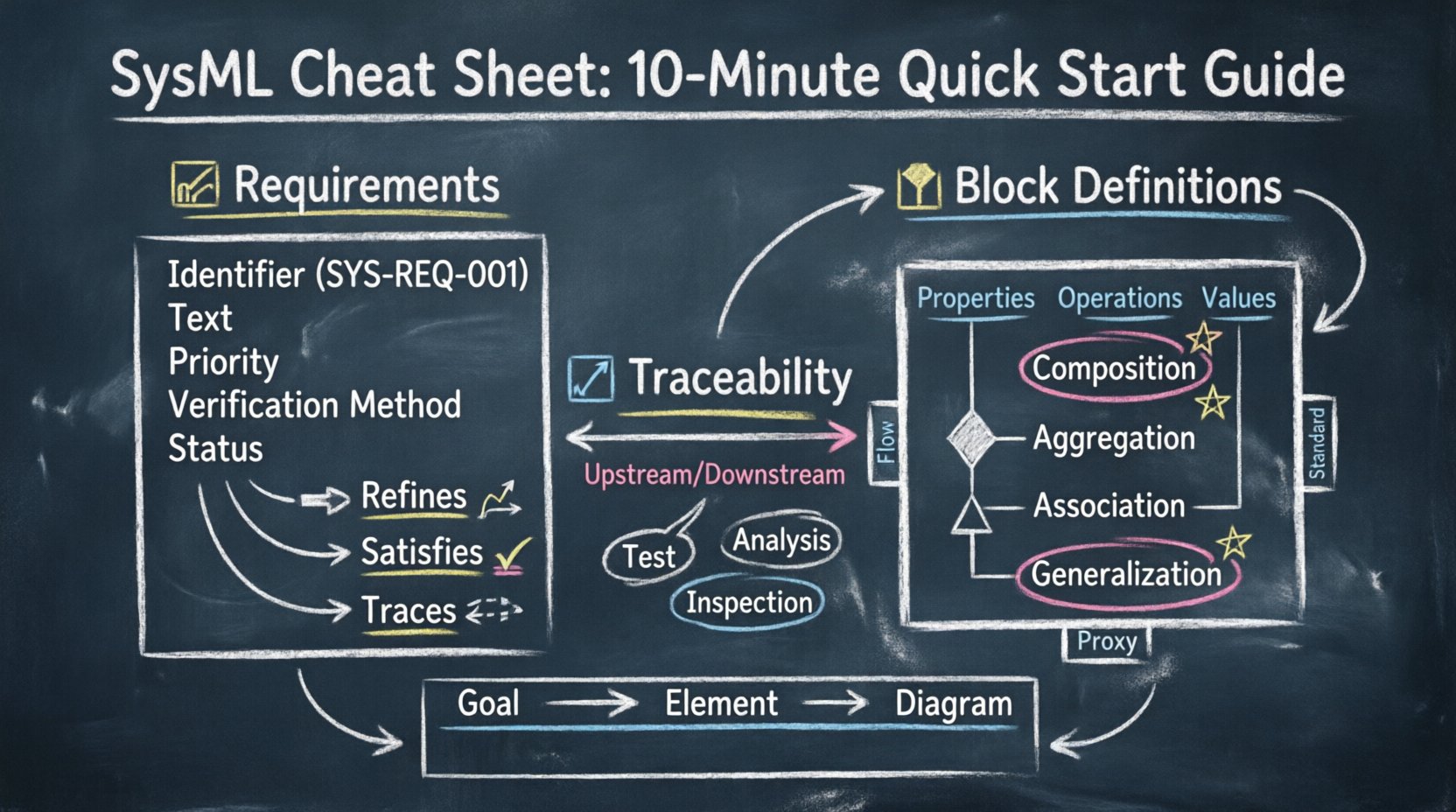
- Identifier: A unique string (e.g., SYS-REQ-001). This is crucial for cross-referencing documents and models.
- Text: The actual statement of the need. Keep this concise and testable.
- Priority: Defines the importance (e.g., Critical, High, Medium, Low).
- Verification Method: How will you prove the requirement is met? Options include Test, Analysis, Inspection, or Demonstration.
- Status: Tracks the lifecycle state (e.g., Draft, Approved, Verified, Baseline).
1.2 Requirement Relationships
Requirements rarely exist in isolation. They relate to one another to form a hierarchy or dependency chain. SysML provides specific relationships to manage these connections.
- Refines: Used to add detail to a higher-level requirement. A child requirement clarifies the parent.
- Satisfies: Links a lower-level requirement to a higher-level one. Often used when a solution element (like a block) fulfills a need.
- DerivesReqs: Indicates that one requirement is derived from another, often due to a change in a parent requirement.
- Aligns: Shows that two requirements are related, typically within different projects or standards.
- Traces: A general relationship to link requirements to other elements like blocks, use cases, or test cases.
1.3 Requirement Diagrams (RD)
While SysML has many diagram types, the Requirement Diagram is specialized for managing the requirement network. It allows you to visualize the flow of needs and their dependencies without cluttering the structural diagrams.
| Relationship | Direction | Usage Context |
|---|---|---|
| Refines | Parent → Child | Breaking down complex needs into specific actions. |
| Satisfies | Block → Requirement | Showing how a design element meets a specific need. |
| DerivesReqs | Parent → Child | Updating child requirements based on changes in the parent. |
| Traces | Flexible | Linking requirements to verification artifacts or other system elements. |
🧱 Part 2: Block Definition Diagrams (BDD)
The Block Definition Diagram is the primary structural diagram in SysML. It defines the system’s composition, internal structure, and external interfaces. Blocks represent the physical or logical entities that make up the system. They can be hardware, software, personnel, or facilities.
2.1 Defining Blocks
A block is the fundamental unit of structure. It encapsulates data and behavior. When you define a block, you are establishing a contract for what that component is and how it interacts.
- Properties: These are the attributes of a block. They define the data the block holds or the sub-components it contains. Properties have a type (e.g., another block, a primitive data type like integer or string).
- Operations: These define the actions a block can perform. While SysML allows behavioral modeling, operations on a block often represent functional capabilities.
- Values: Constant values assigned to properties. Useful for configuration parameters.
2.2 Structural Relationships
Blocks connect to one another to form a system. These connections define the flow of data, energy, or material. The type of relationship dictates the strength of the connection.
- Composition: A strong ownership relationship. The part cannot exist without the whole. If the composite block is deleted, the parts are deleted. Visually, a filled diamond represents this.
- Aggregation: A weak ownership relationship. The part can exist independently of the whole. Visually, an open diamond represents this.
- Association: A connection between blocks without ownership. It represents a usage relationship or a data flow. Visually, a simple line represents this.
- Generalization: Inheritance. A specialized block (child) inherits properties from a generalized block (parent). Visually, a hollow triangle represents this.
2.3 Block Properties and Ports
Interfaces are critical for defining how blocks interact. You should avoid exposing internal implementation details to other blocks. Instead, use ports.
- Flow Ports: Represent the flow of physical quantities (e.g., electricity, fluid, data). They define the direction of flow into or out of the block.
- Standard Ports: Represent functional interfaces. They define operations or services the block provides or requires.
- Proxy Ports: Used to represent an interface provided or required by an internal part of the block, exposing it to the outside world.
| Relationship Type | Cardinality | Example Scenario |
|---|---|---|
| Composition | 1 to Many | An Engine composed of Pistons. |
| Aggregation | 1 to Many | A Fleet of Vehicles. |
| Association | 0..1 to Many | A Pilot assigned to a Vehicle. |
| Generalization | 1 to 1 | A Sedan is a type of Car. |
🔗 Part 3: Traceability and Verification
Modeling is not complete without traceability. Traceability links requirements to the design elements that satisfy them. This ensures that every need has a corresponding implementation and that every implementation serves a need.
3.1 The Trace Link
The trace relationship connects any two model elements. In the context of requirements and blocks, it is the most critical link. It answers the question: Does this design element meet that requirement?
- Upstream Trace: Links a design element back to a requirement. This ensures the design is grounded in stakeholder needs.
- Downstream Trace: Links a requirement to a design element. This ensures the need is addressed in the architecture.
- Impact Analysis: If a requirement changes, trace links show which blocks are affected. This reduces the risk of unintended side effects during modifications.
3.2 Verification and Validation
Traceability extends to verification. You must link requirements to verification activities. This confirms that the system works as intended.
- Test Cases: Link requirements to specific test procedures. A requirement should be traceable to at least one test.
- Analysis: Mathematical or simulation-based verification.
- Inspection: Visual or manual checking of the model or physical artifact.
Without these links, the model is merely a drawing. With them, it becomes a verified specification.
⚙️ Part 4: Best Practices for Structure
Adopting a consistent approach to modeling prevents confusion and ensures maintainability. Follow these guidelines to keep your model clean and usable.
4.1 Naming Conventions
Consistency in naming is vital. Use a standard format for identifiers and names.
- Prefixes: Use prefixes to distinguish types (e.g., REQ- for requirements, BLK- for blocks).
- Case Sensitivity: Decide on a convention (e.g., CamelCase or snake_case) and stick to it.
- Uniqueness: Ensure no two elements share the same name within the same namespace.
4.2 Hierarchy and Decomposition
Do not create a flat structure. Decompose complex systems into manageable subsystems.
- Top-Down: Start with the system level and decompose into subsystems. This helps in managing complexity.
- Bottom-Up: Sometimes existing components must be integrated. Use aggregation to link them to the top-level system.
- Boundaries: Clearly define the boundary of each block. What is inside the block? What is outside?
4.3 Managing Change
System requirements change. Your model must adapt.
- Version Control: Keep track of changes to requirements and blocks. Document the reason for changes.
- Baselines: Create baselines at key milestones. This allows you to revert or compare against previous states.
- Impact Assessment: Before deleting a block or requirement, check its trace links. Deletion might break the verification chain.
🛠️ Part 5: Common Pitfalls to Avoid
Even experienced engineers can fall into modeling traps. Recognizing these early saves significant time later.
5.1 Over-Modeling
Creating a model with too much detail for the current phase is a common error. SysML allows deep detail, but it is not always necessary. Focus on the level of abstraction required for the current decision-making point.
5.2 Mixing Concerns
Do not mix behavioral and structural information in the same diagram unnecessarily. While SysML allows this, it often leads to clutter. Keep structure in BDD and behavior in Internal Block Diagrams (IBD) or Activity Diagrams.
5.3 Ignoring Interfaces
Defining blocks without defining their interfaces creates a disconnected model. If a block does not have ports or properties defined, it cannot be integrated. Always define the interface before connecting blocks.
5.4 Inconsistent Traceability
Leaving gaps in traceability is risky. A requirement without a satisfying block is a technical debt. A block without a requirement is scope creep. Ensure every link has a purpose.
📊 Part 6: Quick Reference Summary
Use this summary table to quickly locate the correct diagram or element for your needs.
| Goal | Element Type | Diagram Type |
|---|---|---|
| Define System Needs | Requirement | Requirement Diagram |
| Define System Structure | Block | Block Definition Diagram |
| Define Internal Connections | Part, Port, Flow | Internal Block Diagram |
| Define Functional Flow | Action, Flow | Activity Diagram |
| Define Interaction | Message, State | Sequence Diagram |
🧭 Part 7: Workflow Integration
Integrating SysML into your engineering workflow requires a shift in perspective. It is not just about drawing; it is about managing information.
7.1 Elicitation Phase
Start by capturing stakeholder needs. Convert these into SysML requirements. Assign unique identifiers immediately. Do not wait to model the structure until the needs are clear.
7.2 Definition Phase
Once needs are clear, define the blocks. Create the high-level BDD. Define the interfaces using ports. Ensure the blocks match the functional requirements.
7.3 Refinement Phase
Break down blocks into subsystems. Use composition to define the hierarchy. Refine requirements into lower-level specifications. Update trace links to reflect the new structure.
7.4 Verification Phase
Link requirements to test cases. Run simulations if applicable. Verify that the block properties meet the requirement constraints. Update the status of requirements to Verified.
❓ Part 8: Frequently Asked Questions
Q: Can I use text boxes in SysML?
A: Yes, but they are not structured elements. For traceability, always use the Requirement element. Text boxes are for notes or comments that do not need to be tracked.
Q: What is the difference between a Block and a Class?
A: SysML is based on UML, so they are similar. However, SysML blocks are designed for systems engineering. They focus on physical properties, parts, and flows, whereas UML classes focus on software logic and methods.
Q: How do I handle multiple stakeholders?
A: Use packages to organize requirements by stakeholder. Use tags to assign ownership. Ensure traceability allows you to see which requirement satisfies which stakeholder’s need.
Q: Is SysML only for hardware systems?
A: No. SysML applies to software, services, personnel, and facilities. It is a general-purpose language for complex systems of any composition.
Q: How do I manage large models?
A: Use packages to compartmentalize the model. Avoid putting everything in the root package. Use views to show only relevant subsets of the model to specific audiences.
📝 Final Thoughts
Effective system modeling relies on disciplined application of language standards. By focusing on Requirements and Block Definitions, you establish a robust foundation for your system architecture. The relationships between these elements drive the integrity of the model.
Remember that the goal is not to create a diagram that looks impressive, but to create a model that communicates clearly. Clarity reduces risk. Reducing risk saves time and resources. This guide provides the structure needed to achieve that clarity.
Continue to refine your model as the system evolves. Keep requirements up to date. Keep block definitions accurate. Maintain the trace links. This ongoing maintenance is what turns a static model into a living engineering asset.
Apply these principles consistently. The complexity of modern systems demands nothing less. With a solid grasp of SysML requirements and blocks, you are equipped to handle the challenges of system integration and design.