A comprehensive reference for systems engineers, software architects, and product managers on creating, understanding, and leveraging sequence diagrams for scenario modeling.
Introduction to Sequence Diagrams
A sequence diagram is a kind of behavior diagram that presents a dynamic view of a use case, requirement, or system. It expresses sequences of behaviors and event occurrences over time, enabling stakeholders to visualize how system components interact to fulfill specific scenarios.
Key Concepts:
-
Lifelines: Model participants in system behavior (objects, actors, components)
-
Messages: Represent interactions and communication between lifelines
-
Interaction Uses: Enable behavioral decomposition across multiple interactions
-
Constraints: Allow specification of time and duration constraints on interactions
SysML Context: SysML includes the Sequence Diagram exclusively, excluding the Interaction Overview Diagram and Communication Diagram due to overlapping functionality. The Timing Diagram is also excluded due to maturity concerns for systems engineering applications.
Why Model Scenarios with Sequence Diagrams?
Understanding Use Cases and Scenarios
A use case is a collection of interactions between external actors and a system, defined as “the specification of a sequence of actions, including variants, that a system (or entity) can perform, interacting with actors of the system.”
A scenario represents one specific path or flow through a use case—describing the sequence of events during a particular execution. Sequence diagrams are the standard notation for representing these scenarios.
Benefits of Visualizing Use Case Scenarios:
| Purpose | Description |
|---|---|
| Modeling the Problem | Understand requirements in detail by creating a model of end-user problems |
| Modeling the Solution | After defining system architecture, visualize how capabilities are delivered by components |
| System Sequence Diagrams | Illustrate high-level interactions between users, systems, and subsystems |
Sequence Diagrams at a Glance: Core Structure
Sequence diagrams are interaction diagrams organized according to time (vertical axis) and objects (horizontal axis).
Object (Lifeline) Dimension

-
Horizontal axis: Shows elements involved in the interaction
-
Object ordering: Conventionally listed left-to-right by participation order (flexible)
-
Lifelines: Represent object existence over time
-
Objects existing throughout: Lifelines drawn parallel to time dimension from top
-
Transient objects: Lifelines begin/end with message receipt
-
Time Dimension
-
Vertical axis: Represents time progressing downward
-
Message ordering: First message at top, last at bottom (sequence numbers optional)
Flow of Control and Message Types
Focus of Control (Activation Bar)

The focus of control (activation bar) illustrates the period during which an object is actively performing an action. Actions may be:
-
Performed directly by the object
-
Delegated to subordinate objects via messages
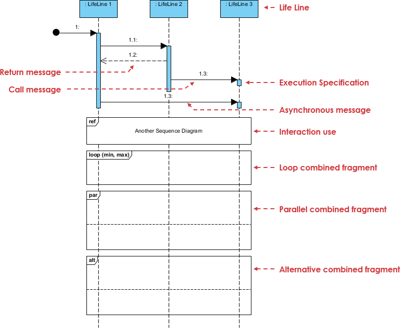
Message Types and Notation
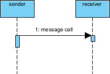
Messages specify communication from one object to another, with an expectation of activity by the recipient. They are drawn horizontally from sender to receiver.
1. Synchronous Message
-
Notation: Solid line with filled arrowhead
-
Use case: Regular operation calls; sender waits for receiver to complete
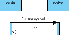
2. Return Message
-
Notation: Dashed line with open arrowhead
-
Use case: Represents response/return value from synchronous call
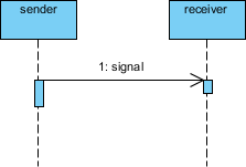
3. Asynchronous Message
-
Notation: Solid line with open arrowhead
-
Use case: Signals/events with no expected reply; sender continues immediately
Object Lifecycle: Creation and Destruction
Participants don’t necessarily exist for the entire interaction duration. Sequence diagrams support dynamic object lifecycle modeling.
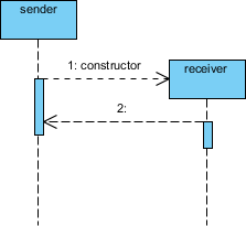
Constructor Message
-
Creates the receiver object
-
Sender exists at interaction start (top of diagram)
-
Target created during interaction appears lower on time axis
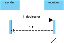
Destructor Message
-
Destroys the receiver object
-
Explicitly used when target destruction is set to ‘after destructor’
-
Alternative: Lifeline ends with large X marker
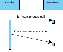
Advanced Notation: Non-Instantaneous Messages
While messages are typically considered instantaneous (horizontal arrows), real-world systems often involve transmission delays.
Non-Instantaneous Message Notation
-
Notation: Slanted arrow
-
Purpose: Indicates measurable time between send and receive events
-
Use case: Network latency, asynchronous processing delays, batch operations
Frames and Combined Fragments
Sequence Frame Notation
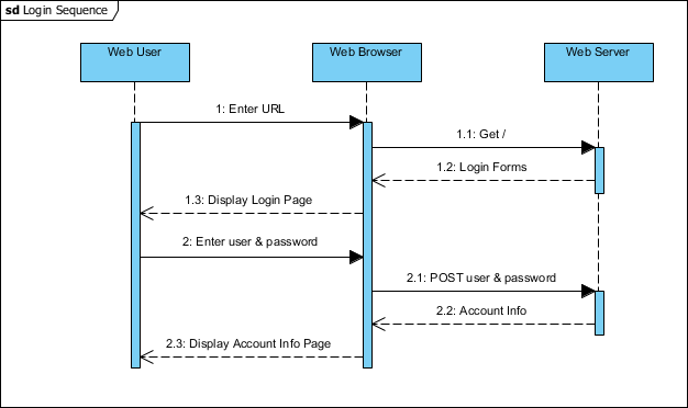
A Sequence Frame provides a boundary enclosing all messages and lifelines of a communication sequence:
-
Drawn as large rectangle with pentagon at top-left
-
Pentagon contains “sd” followed by sequence name
-
Example: Encloses user login interaction between User, Browser, and Web Server
Sequence Diagram Fragments (Combined Fragments)
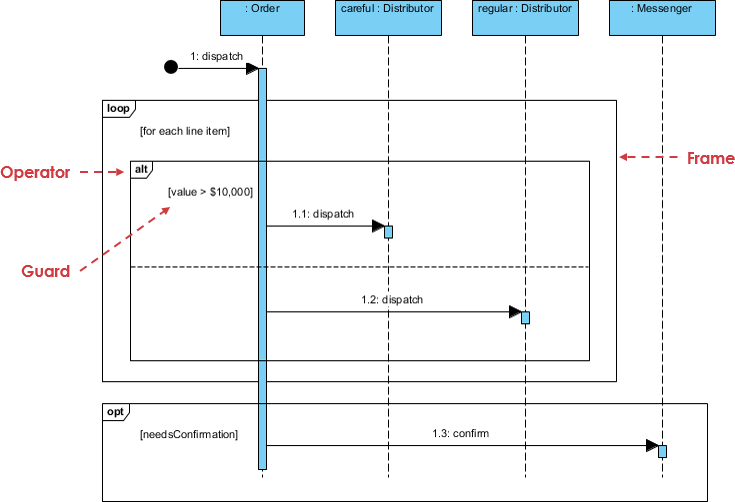
UML 2.0 introduced interaction fragments to add semantic richness:
-
Represented as boxes enclosing portions of interactions
-
Fragment operator (top-left corner) indicates fragment type
-
Enables modeling of complex logic without cluttering the diagram
Modeling Logic: Loops, Conditions, and Alternatives
⚠️ Best Practice Note: Sequence diagrams excel at visualizing object interactions, not control logic. For complex algorithms, consider Activity Diagrams or code. Use fragments sparingly for clarity.
Fragment Types Reference Table
| Fragment | Description | Use Case |
|---|---|---|
| alt | Alternative: Only the fragment with true condition executes | If/else branching |
| opt | Optional: Executes only if condition is true | Single conditional path |
| par | Parallel: Fragments run concurrently | Multi-threaded operations |
| loop | Loop: Fragment repeats; guard indicates iteration basis | For/while loops |
| region | Critical region: Only one thread executes at once | Synchronization blocks |
| neg | Negative: Shows invalid/forbidden interaction | Error scenarios, constraints |
| ref | Reference: Links to interaction in another diagram | Reuse, modularity |
| sd | Sequence diagram: Surrounds entire diagram | Top-level framing |
Practical Example: Place Order Scenario
Scenario Description
A ship member places an online order. Delivery method (courier vs. ordinary mail) depends on membership status (VIP vs. Ordinary). Optionally, a confirmation notice is sent if the member enabled notifications.
Sequence Diagram
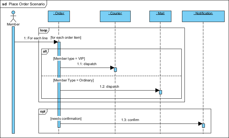
Key Modeling Techniques Demonstrated:
-
alt fragment: Branches based on
memberStatus == VIP -
opt fragment: Conditional confirmation email based on
notificationOptIn -
Activation bars: Show processing duration for each component
-
Synchronous/Asynchronous messages: Distinguish between blocking calls and fire-and-forget signals
-
Lifeline ordering: Logical flow from User → Frontend → Backend → Shipping Service
AI-Powered Sequence Diagram Generation
Modern tools like Visual Paradigm integrate generative AI to accelerate sequence diagram creation, combining standard modeling with intelligent automation.
AI-Powered Features
🤖 Generate-from-Text Engine
Convert plain text prompts into structured diagrams:
Prompt: "A user logs in, selects a product, and checks out"
→ Auto-generates actors, lifelines, and message flows
✨ AI Refinement Tool
Transform high-level diagrams or code snippets (Mermaid/PlantUML) into detailed, multi-layered representations:
-
Automatic decomposition into architectural layers (e.g., MVC)
-
Semantic enrichment of message types and constraints
💬 Conversational Editing
Modify diagrams using natural language commands:
-
“Add a payment gateway”
-
“Rename User to Customer”
-
“Add an alternative path for failed payment”
🧠 Intelligent Design Feedback
AI analyzes diagrams to suggest improvements:
-
Identify synchronous calls that could be asynchronous
-
Detect potential bottlenecks or race conditions
-
Recommend fragmentation for readability
🎨 Automatic Layout
AI engine ensures optimal spacing, alignment, and readability—automatically arranging complex interactions so you focus on logic, not layout.
Core Modeling Support & Best Practices
Beyond AI, professional-grade tools provide precise system modeling capabilities.
UML 2.x Compliance
-
Full support for combined fragments:
alt,loop,opt,break,par,ref -
Advanced notation: activation bars, creation/destruction markers, time constraints
Visual Logic Representation
-
Specialized cues for processing states
-
Clear differentiation between message types and control flow
Traceability & Integration
-
Link sequence diagrams to Use Cases, requirements, and other artifacts
-
Maintain system-wide consistency across modeling views
Collaboration & Export
| Feature | Benefit |
|---|---|
| Cloud-Based Sharing | Real-time team reviews and concurrent design via Visual Paradigm Cloud |
| Export Formats | PNG, SVG, PDF, JSON for reports and documentation |
| Desktop & Online Sync | Move AI-generated drafts from web chatbot to desktop for advanced editing |
Best Practices Checklist
✅ Start with a clear scenario scope (one use case flow per diagram)
✅ Limit lifelines to essential participants (avoid clutter)
✅ Use fragments judiciously—prefer simplicity over exhaustive logic
✅ Label messages with operation names and parameters
✅ Annotate time constraints where timing is critical
✅ Maintain consistent naming conventions across diagrams
✅ Link diagrams to requirements for traceability
- Reference
- AI Sequence Diagram Generator: How Visual Paradigm Transforms Your Modeling Workflow: Comprehensive review of Visual Paradigm’s AI-powered sequence diagram generation capabilities and workflow transformation benefits.
- UML Sequence Diagram: A Definitive Guide to Modeling Interactions with AI: Official guide covering sequence diagram fundamentals, notation reference, and AI-assisted modeling techniques.
- AI Sequence Diagram Refinement Tool: Feature documentation for transforming high-level diagrams or code snippets into detailed, multi-layered sequence models.
- Comprehensive Review: Visual Paradigm’s AI Diagram Generation Features: Independent analysis of AI capabilities including text-to-diagram generation, conversational editing, and intelligent feedback.
- Comprehensive Review: Visual Paradigm’s AI Diagram Generation Features (Part 2): Extended evaluation covering collaboration features, export options, and integration workflows.
- Sequence Diagram Refinement Tool (AI): Direct access to the AI refinement tool for enhancing existing sequence diagrams with architectural decomposition.
- AI Chatbot for Diagram Generation: Overview of the conversational AI interface for generating and editing diagrams using natural language prompts.
- UML Sequence Diagram Guide with AI: Interactive documentation combining traditional UML guidance with AI-powered modeling assistance.
- AI Diagram Generation Platform: Central hub for Visual Paradigm’s AI diagram generation capabilities across multiple diagram types.
- Visual Paradigm Platform Overview: General platform description highlighting visual modeling, business analysis, and AI integration features.
- AI Sequence Diagram Example: Online Payment Processing System: Practical example demonstrating AI-generated sequence diagrams for e-commerce payment workflows.
- AI Sequence Diagram Generator Workflow Transformation: Case study on productivity gains and modeling accuracy improvements using AI-assisted sequence diagrams.
- Visual Paradigm Official Website: Primary resource for product features, documentation, tutorials, and community support for UML/SysML modeling.
- Visual Paradigm Tutorial Video: Video demonstration of sequence diagram creation and AI-assisted modeling workflows.
- Use Case to Activity Diagram Transformation: Guide on linking use cases to behavioral diagrams, complementing sequence diagram modeling for end-to-end scenario coverage.
💡 Pro Tip: Start simple. Model your primary success scenario first. Then iteratively add alternative flows using alt/opt fragments. Validate with stakeholders early—sequence diagrams are powerful communication tools, not just documentation artifacts.