The landscape of software engineering has shifted dramatically. We moved from monolithic structures to distributed systems where independence, scalability, and resilience are paramount. Microservices architecture represents this shift, breaking down complex applications into smaller, manageable services. However, with this complexity comes a significant challenge: visualization and understanding the relationships between these services.
UML Package Diagrams offer a standardized method to represent the high-level organization of a system. In the context of microservices, they serve as the blueprint for logical boundaries, dependencies, and data flow. This guide explores how these diagrams evolve to support modern distributed systems, ensuring clarity without the noise of implementation details.
📦 Understanding UML Package Diagrams
A UML Package Diagram is a structural diagram used to organize elements into groups. It is essentially a container diagram. In traditional software design, packages grouped related classes or functions. In the microservices era, the definition of a “package” shifts to represent a service, a domain, or a functional boundary.
These diagrams provide a view of the system that is independent of the physical implementation. They focus on:
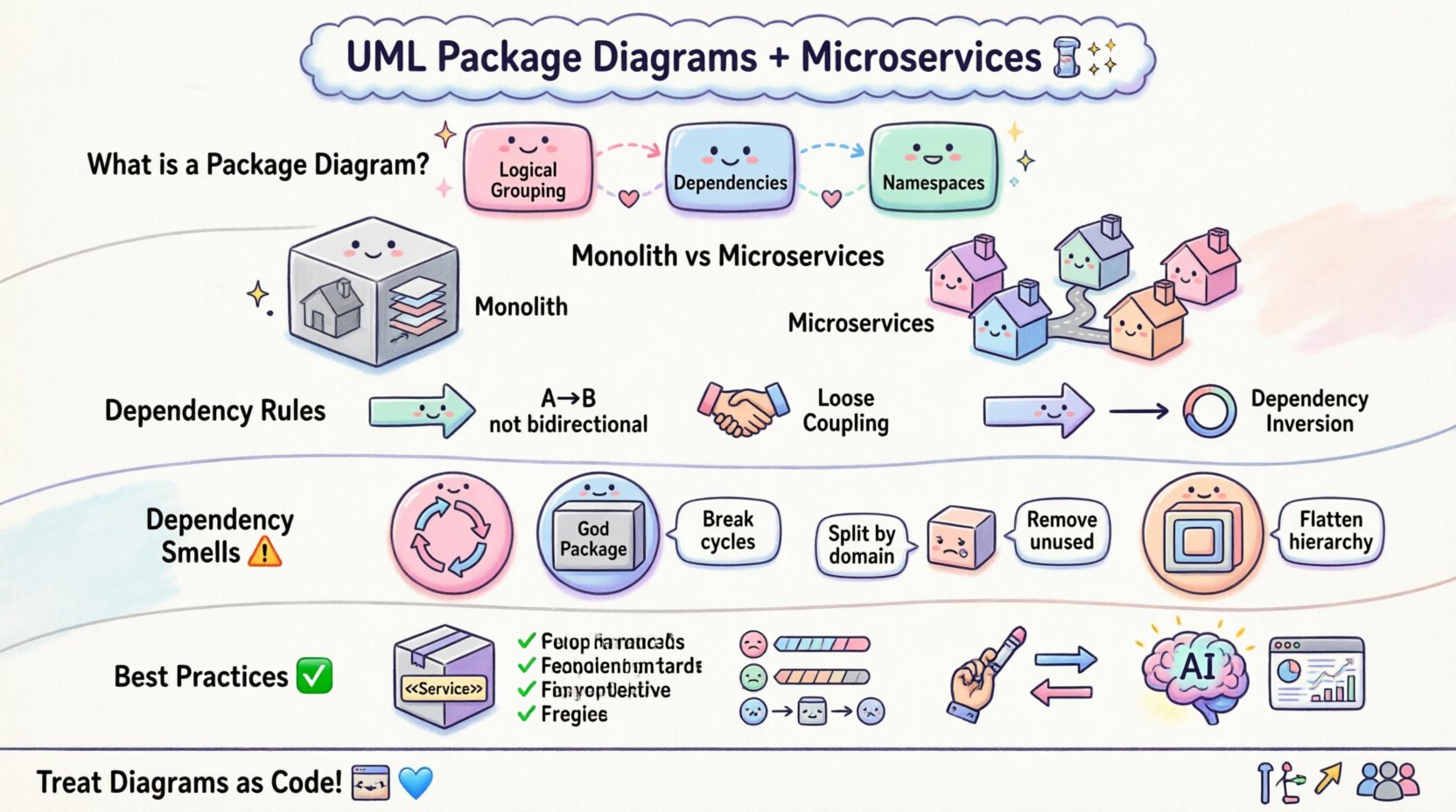
- Logical Grouping: Grouping related functionality together.
- Dependencies: Showing how one group interacts with another.
- Namespaces: Defining the scope of visibility for elements.
Unlike a class diagram, which details attributes and methods, a package diagram remains at a higher level of abstraction. This abstraction is critical when dealing with dozens or hundreds of microservices. It allows architects to see the forest rather than getting lost in the trees.
🏗️ Mapping Packages to Microservices
The core challenge in microservices architecture is defining boundaries. Too coarse, and you reintroduce monolithic coupling. Too fine, and you introduce communication overhead and operational complexity. UML Package Diagrams help visualize these boundaries.
Each package in the diagram often corresponds to a bounded context in Domain-Driven Design. This alignment ensures that the software structure reflects the business structure. When a package represents a microservice, the diagram clarifies:
- Ownership: Which team is responsible for which package?
- Scope: What functionality resides within the package?
- Exposure: What interfaces are exposed to other packages?
This mapping creates a single source of truth for the architectural layout. It prevents the scenario where services grow organically into an unmanageable web of dependencies. By enforcing strict package boundaries in the diagram, teams can enforce strict boundaries in the code.
🔗 Managing Dependencies and Coupling
Dependency management is the heartbeat of a healthy microservices ecosystem. In a package diagram, dependencies are represented by arrows pointing from the dependent package to the dependent package. The direction matters significantly.
Consider the following principles when drawing these dependencies:
- Directed Relationships: Avoid bidirectional arrows where possible. If Service A needs data from Service B, the dependency is A to B.
- Loose Coupling: Packages should rely on interfaces or contracts, not internal implementations.
- Dependency Inversion: High-level packages should not depend on low-level details. They should depend on abstractions.
Visualizing these relationships helps identify circular dependencies. A cycle in a package diagram indicates a logical deadlock that must be resolved before deployment. It signals that two services are too tightly coupled and should be refactored to communicate via asynchronous messaging or shared contracts.
🔄 Evolution: Monolith vs. Microservices Modeling
The way we model packages has changed over the last decade. In monolithic applications, packages were often organized by layer (Controller, Service, Repository). In microservices, the organization shifts to business capabilities.
The table below outlines the structural differences in modeling approaches:
| Feature | Monolithic Package Structure | Microservices Package Structure |
|---|---|---|
| Organization | By Technical Layer (UI, Logic, Data) | By Business Domain (Order, Inventory, User) |
| Deployment | Single Package Deployed Together | Each Package Deploys Independently |
| Communication | Direct Method Calls | Network Protocols (HTTP, gRPC, MQ) |
| Scope | Global Namespace | Isolated Namespaces per Service |
This shift requires a rethinking of how package diagrams are maintained. Static diagrams that are created once and forgotten are no longer sufficient. The diagram must evolve as the system evolves.
🤔 Challenges in Visualization
While UML Package Diagrams provide clarity, they introduce specific challenges in a dynamic environment. Microservices are often deployed, updated, and scaled independently. The static nature of a diagram can lead to documentation drift.
Common challenges include:
- Versioning: How to represent multiple versions of a service in the diagram?
- Dynamic Discovery: Service discovery mechanisms change runtime dependencies, which static diagrams cannot capture.
- Granularity: Determining when a package is a service versus a module within a service.
- Tooling Overhead: Maintaining diagrams manually becomes a bottleneck as the system scales.
To mitigate these issues, architects must focus on the “Contract First” approach. The package diagram should describe the interface and the contract, not the internal logic. This ensures that changes inside a service do not invalidate the package diagram, provided the contract remains stable.
✅ Best Practices for Documentation
To ensure the package diagram remains a useful asset rather than a burden, follow these structured practices:
- Use Stereotypes: Extend the UML notation with stereotypes like <<Service>>, <<API>>, or <<Database>> to clarify the role of each package.
- Limit Depth: Do not nest packages more than three levels deep. Deep nesting obscures the top-level architecture.
- Color Coding: Use visual cues to indicate status, ownership, or criticality without using CSS.
- Link to Artifacts: Reference the source code repository or API documentation directly within the package label.
Adhering to these practices keeps the diagram readable. It allows a new developer to understand the system architecture within minutes rather than hours.
📊 Common Dependency Smells
When analyzing package diagrams, certain patterns indicate technical debt. Recognizing these “smells” early prevents architectural collapse.
| Pattern | Implication | Remediation |
|---|---|---|
| Circular Dependency | Service A calls B, B calls A | Introduce an intermediary or message queue |
| God Package | One package depends on everything | Refactor into smaller, focused packages |
| Unused Package | Package has no incoming dependencies | Remove or re-evaluate necessity |
| Deep Nesting | Complex hierarchy of sub-packages | Flatten structure to improve visibility |
Regular audits of these diagrams against the actual codebase help maintain integrity. Automated tools can scan the code and compare it against the diagram to highlight discrepancies.
🔮 Future Trends in Modeling
The future of UML Package Diagrams in microservices lies in automation and integration. As systems become more complex, manual drawing is no longer sustainable. We are moving towards diagram-as-code.
Key trends include:
- Auto-Generation: Tools that parse code repositories to generate package diagrams automatically.
- Real-Time Updates: Diagrams that update as the CI/CD pipeline runs, reflecting the current state of the architecture.
- AI-Assisted Refactoring: Systems that suggest package reorganizations based on dependency metrics.
- Integration with Observability: Linking logical packages to runtime metrics like latency and error rates.
This evolution ensures that the diagram remains a living document. It stops being a static snapshot and becomes a dynamic view of the system’s health and structure.
🛠️ Implementation Strategy
Adopting this modeling approach requires a strategic plan. It is not about drawing diagrams for the sake of drawing them. It is about enabling better decision-making.
The implementation process typically follows these steps:
- Inventory Existing Services: Map all current microservices and their responsibilities.
- Define Packages: Group services into logical packages based on domain boundaries.
- Map Dependencies: Draw the arrows showing how packages interact.
- Review and Refine: Have architects review the diagram for violations of dependency rules.
- Integrate into Workflow: Make the diagram part of the pull request or deployment checklist.
By integrating the diagram into the workflow, it becomes a guardrail. It prevents developers from introducing dependencies that violate the architectural vision.
🧠 Cognitive Load and Team Alignment
Beyond technical constraints, package diagrams address human factors. Microservices often span multiple teams. A clear package diagram acts as a contract between these teams.
It reduces cognitive load by:
- Clarifying Boundaries: Teams know exactly what they own and what they must not touch.
- Reducing Meetings: Clear documentation reduces the need for sync meetings to explain architecture.
- Onboarding: New hires can grasp the system structure quickly.
When teams understand the boundaries, they can innovate faster. They do not need to worry about breaking unrelated parts of the system. This autonomy is the true value of a well-structured package diagram.
📈 Final Perspectives
The role of UML Package Diagrams in microservices architecture is evolving. They are no longer just static drawings but dynamic representations of system health and boundaries. As the industry moves towards event-driven architectures and serverless computing, the need for clear logical packaging increases.
Success in this area depends on discipline. Teams must resist the temptation to ignore the diagram when deadlines are tight. The diagram is the map; the code is the territory. If the map is wrong, the territory becomes lost.
By focusing on boundaries, dependencies, and contracts, architects can build systems that are resilient, scalable, and maintainable. The package diagram remains a vital tool in this journey, providing the structure needed to navigate the complexity of modern distributed systems.
Future-proofing your architecture involves treating these diagrams as code. Version them, review them, and automate their generation where possible. This approach ensures that your architectural vision survives the inevitable changes of software development.