Understanding how a system behaves is just as critical as understanding what data it stores. In the world of software engineering and systems analysis, visualizing interactions is key. The Use Case Diagram stands out as a primary tool for capturing functional requirements. It bridges the gap between technical teams and stakeholders by depicting the “who” and the “what” without getting bogged down in the “how.” This guide provides a deep dive into the anatomy of these diagrams, exploring every element that makes them effective communication tools.
🎯 What Is a Use Case Diagram?
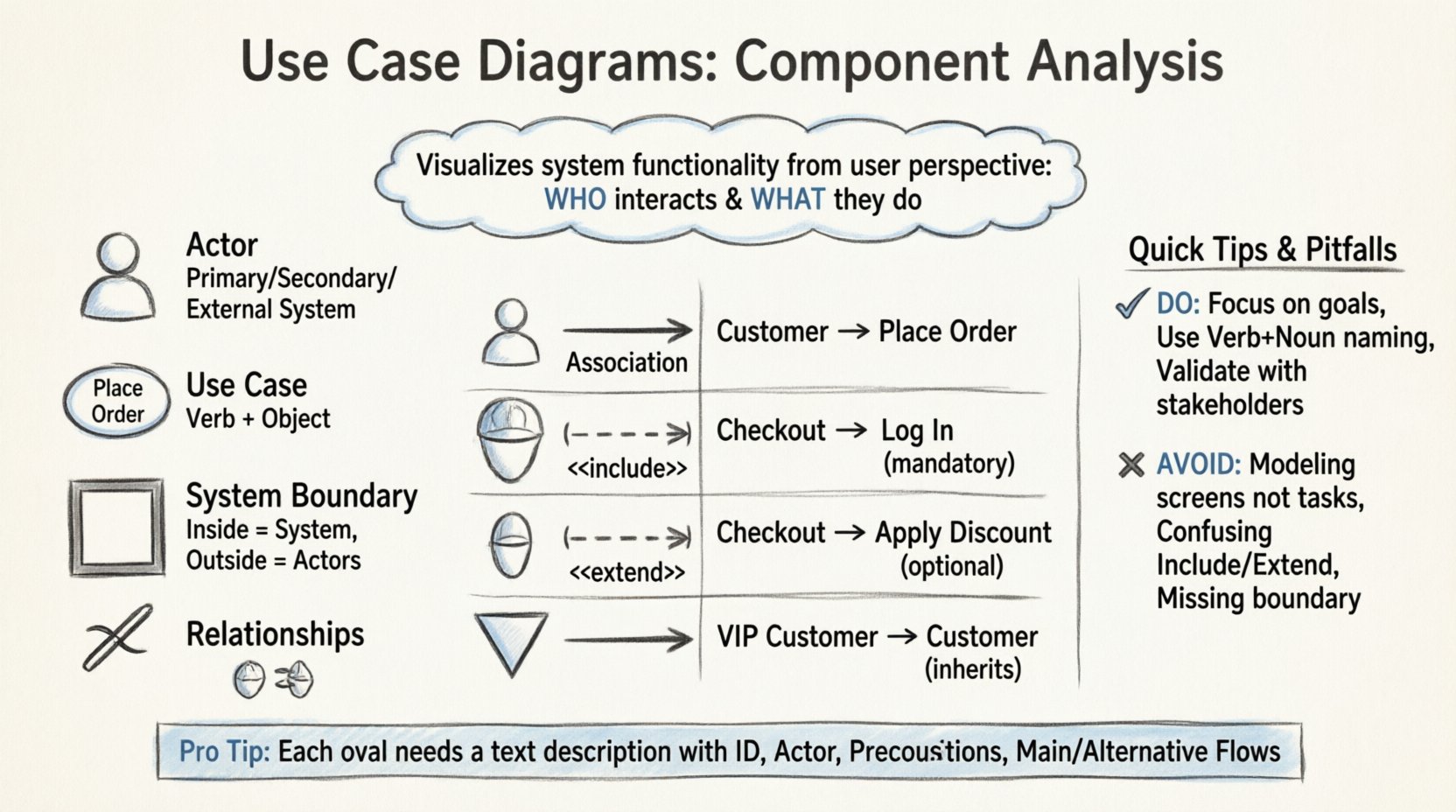
A Use Case Diagram is a type of Unified Modeling Language (UML) diagram. Its primary purpose is to describe the functionality of a system from the perspective of an external observer. Unlike structural diagrams that focus on static elements like classes or databases, this diagram focuses on dynamic behavior. It answers specific questions:
- Who interacts with the system?
- What actions can these users perform?
- How do these actions relate to one another?
These diagrams are essential during the requirements gathering phase. They help identify the scope of a project and ensure that all necessary features are accounted for before coding begins. By focusing on user goals, they prevent the common pitfall of designing features that users do not actually need.
🧩 Core Components of a Use Case Diagram
To construct a clear and effective diagram, one must understand the fundamental building blocks. Every valid diagram relies on a specific set of symbols. Each symbol carries a distinct meaning regarding the system’s architecture.
1. Actors 👤
An actor represents a role played by a user or an external system that interacts with the software. It is crucial to remember that an actor is not a specific person, but a role. One individual might play multiple roles, and multiple individuals might share one role.
- Primary Actors: These initiate the interaction to achieve a specific goal. They are usually the main beneficiaries of the system.
- Secondary Actors: These systems or users support the primary actors. They do not initiate the use case but provide necessary resources.
- External Systems: Sometimes, a third-party service acts as an actor. For example, a payment gateway in an e-commerce application.
Actors are typically depicted as stick figures. The placement of the actor outside the system boundary indicates that they exist independently of the software being modeled.
2. Use Cases 🎬
A use case represents a specific function or service provided by the system. It is a complete unit of functionality that delivers value to an actor. It is not a single screen or a button click, but rather a task that accomplishes a goal.
- Representation: Drawn as an oval shape.
- Labeling: Should follow a “Verb + Object” format (e.g., “Place Order” or “Generate Report”).
- Scope: Must stay within the system boundary. If it requires external logic, it belongs to a different actor or system.
3. System Boundary 🧱
The system boundary defines the scope of the software being modeled. It is usually represented by a rectangle. Everything inside the rectangle is part of the system. Everything outside is an actor or an external dependency.
- Clarity is vital here. The boundary helps distinguish internal processes from external interactions.
- It allows stakeholders to see what is included in the current version of the product versus what is outside the scope.
4. Relationships 🔗
Lines connect actors to use cases and use cases to other use cases. These lines define the nature of the interaction. There are four standard types of relationships used in this modeling technique.
🔗 Understanding Relationship Types
The connections between elements dictate the logic of the system. Misinterpreting these lines can lead to significant errors in development. Below is a detailed breakdown of each relationship type.
| Relationship | Symbol | Meaning | Example |
|---|---|---|---|
| Association | Solid Line | Communication between actor and use case. | A Customer places an Order. |
| Include | Dashed Line + <<include>> | Mandatory behavior. The base use case always invokes the included use case. | “Log In” is included in “Checkout”. |
| Extend | Dashed Line + <<extend>> | Optional behavior. The extending use case adds behavior under specific conditions. | “Apply Discount” extends “Checkout” if code is valid. |
| Generalization | Solid Line + Hollow Triangle | Inheritance. A child actor or use case inherits the behavior of a parent. | “VIP Customer” is a Generalization of “Customer”. |
Association Lines
This is the most basic connection. It shows that an actor can initiate or participate in a use case. The direction of the association does not always imply data flow; it implies interaction capability. A simple line connects the stick figure to the oval.
Include Relationships
The “Include” relationship extracts common functionality into a separate use case to avoid duplication. This promotes reusability. If Use Case A includes Use Case B, then Use Case B must be executed whenever Use Case A is executed.
- Scenario: Imagine a library system. Both “Borrow Book” and “Renew Book” require the user to “Authenticate.” Instead of drawing “Authenticate” inside both ovals, you create a single “Authenticate” use case and link both with an Include relationship.
- Benefit: This keeps the diagram clean and ensures that if authentication logic changes, it is updated in one place.
Extend Relationships
Extending is the opposite of including in terms of necessity. It represents optional behavior. The extending use case only runs if a specific condition is met. This is often used for error handling or special cases.
- Scenario: In an online store, “Pay with Credit Card” is the base use case. “Pay with Gift Card” extends this use case. It only happens if the user selects that specific option.
- Trigger: An extend relationship usually has a trigger condition associated with it. Without the trigger, the extension does not occur.
Generalization (Inheritance)
This relationship models hierarchy. It allows you to define commonalities in one place and specialize them in another. This is useful when dealing with complex user roles or similar functional flows.
- Actor Generalization: A “Manager” is a type of “Employee.” If “Employee” can “Approve Request,” then “Manager” can also do this, plus potentially “Reject Request.”
- Use Case Generalization: “Make Payment” is a general use case. “Pay by Wire Transfer” and “Pay by Check” are specific implementations of that general case.
📝 Writing Effective Use Case Descriptions
A diagram alone is often not enough. Each oval on the diagram should ideally be supported by a text description. This text provides the necessary detail that the visual symbols cannot convey. A well-written description ensures that developers understand the exact logic required.
Every use case description should contain the following sections:
- Use Case ID: A unique identifier (e.g., UC-001) for tracking.
- Name: A clear, concise title.
- Primary Actor: Who starts this process?
- Preconditions: What must be true before this use case starts? (e.g., “User must be logged in.”)
- Postconditions: What is the state of the system after this use case completes? (e.g., “Order is saved to database.”)
- Main Flow: The primary sequence of steps. This is the “Happy Path” where everything goes right.
- Alternative Flows: Variations in the main flow. What happens if the user cancels? What if the network fails?
- Exception Flows: Handling unexpected errors or system failures.
By detailing the steps, you reduce ambiguity. Developers do not have to guess what happens during an error state. This documentation serves as a foundation for creating test cases later in the development lifecycle.
🛠 Best Practices for Diagramming
Creating a diagram is an iterative process. To maintain quality and utility, adhere to the following guidelines.
1. Focus on Goals, Not Screens
Do not model individual screen interactions. A use case should be a goal-oriented task. “Click Submit Button” is not a use case. “Submit Application” is. If you model screens, the diagram becomes cluttered and loses its high-level overview value.
2. Keep Actors Distinct
Do not create too many actors. If two actors have the exact same interactions with the system, they should be merged into one role. Conversely, ensure distinct roles are not lumped together if they have different permissions or goals.
3. Avoid Over-Complexity
A diagram with fifty use cases is hard to read. If the diagram becomes too complex, consider splitting it. You might create a high-level overview diagram and a detailed diagram for a specific subsystem. Clarity trumps completeness in visual communication.
4. Use Consistent Naming
Ensure that naming conventions are consistent across the entire project. If you use “Verb + Noun” for one use case, do not switch to “Noun + Verb” for another. This consistency helps stakeholders navigate the diagram quickly.
5. Validate with Stakeholders
A diagram is useless if the business team disagrees with it. Review the diagram with the people who know the business processes best. They will spot missing use cases or incorrect assumptions about actor roles that technical teams might overlook.
🚫 Common Pitfalls to Avoid
Even experienced analysts make mistakes when modeling systems. Being aware of common traps can save time during the review process.
- Modeling Data, Not Behavior: Do not draw entities like “Customer” or “Product” as use cases. These are nouns. Use cases must be actions. “Manage Customer” is an action; “Customer” is a data object.
- Too Much Detail: Do not list every single step inside the oval. Keep the diagram high-level. Put the details in the text description.
- Mixing Internal and External: Do not draw internal system processes as use cases. Internal processes are implementation details. Use cases are external interactions.
- Missing System Boundary: Always define the boundary. Without it, it is unclear what is part of the system and what is part of the environment.
- Confusing Include and Extend: Remember the rule of thumb: Include is mandatory. Extend is optional. If you are unsure, check if the behavior happens every time (Include) or only sometimes (Extend).
🔄 Maintenance and Evolution
Software is rarely static. Requirements change, features are added, and old ones are removed. The diagram must evolve with the system. Treating a Use Case Diagram as a static artifact created once at the start of a project is a mistake.
- Version Control: Keep track of diagram versions. When a major change occurs, update the diagram and note the change log.
- Continuous Review: During sprint planning or backlog refinement, refer back to the diagram. Does the new feature fit into the existing model? Does it require a new actor?
- Documentation Linkage: Ensure the diagram links to the detailed use case descriptions. If the description changes, the diagram should be updated to reflect any structural changes.
📈 Integration with Other Models
A Use Case Diagram does not exist in isolation. It is part of a larger ecosystem of models. Understanding how it fits with other diagrams enhances the overall system design.
- Sequence Diagrams: Once a use case is defined, a sequence diagram can be created to show the message flow between objects during that use case.
- Activity Diagrams: For complex use cases with many decision points, an activity diagram can detail the workflow logic more granularly than a use case description.
- Class Diagrams: The entities mentioned in use cases often translate into classes in the object-oriented design. This ensures the data model supports the required behaviors.
By integrating these models, you create a cohesive blueprint. The Use Case Diagram acts as the entry point, guiding the team toward the specific behavioral and structural details required for implementation.
🎓 Summary of Key Takeaways
Creating a robust Use Case Diagram requires a balance of technical precision and clear communication. It is the map that guides the development team through the functional requirements. By correctly identifying actors, defining clear use cases, and utilizing relationships like Include and Extend, you create a blueprint that is easy to understand and modify.
Remember that the goal is not to create a perfect picture immediately, but to facilitate understanding. Regular reviews, clear descriptions, and adherence to best practices ensure that the diagram remains a useful tool throughout the project lifecycle. When stakeholders and developers share a common visual language, the path to a successful product becomes significantly clearer.
Focus on the user’s journey. Keep the diagram clean. Prioritize clarity over complexity. This approach will yield diagrams that serve their purpose effectively: defining what the system does, and why it does it.