In the landscape of software development and systems analysis, visual communication stands as a critical bridge between technical teams and stakeholders. Among the various modeling tools available, the use case diagram remains a fundamental artifact for defining system behavior. It serves not merely as a drawing, but as a contract of functionality. For those new to the discipline, understanding how to construct and interpret these diagrams is essential for ensuring that software solutions meet actual user needs.
This guide provides a deep dive into the mechanics, principles, and best practices surrounding use case diagram components. We will explore how to identify actors, define boundaries, and map relationships without relying on specific tools. The focus remains on the conceptual integrity of the model.
Understanding the Core Purpose 🎯
A use case diagram visualizes the interactions between users and a system. It answers the question: “What can the system do for the user?” rather than “How does the system do it?” This distinction is vital. While sequence diagrams or class diagrams delve into internal logic and data structures, the use case diagram stays at the level of functional requirements.
Key benefits include:
- Clarity: Stakeholders can review requirements without needing technical coding knowledge.
- Scope Definition: It clearly delineates what is inside the system boundary and what is external.
- Communication: It acts as a shared vocabulary between business analysts, developers, and clients.
- Gap Analysis: It helps identify missing features early in the design phase.
Essential Components of a Use Case Diagram 🧩
To build a robust model, one must understand the fundamental building blocks. Each element serves a specific semantic purpose.
1. The Actor 👤
An actor represents a role played by an entity that interacts with the system. Actors are not necessarily people; they can be other systems, hardware devices, or external services. They exist outside the system boundary.
- Human Actors: End users, administrators, or managers.
- System Actors: Another application or a database service.
- Time-Based Actors: Triggers that occur at specific intervals (e.g., a timer).
When naming actors, avoid specific titles like “John.” Instead, use generic roles such as “Customer,” “Admin,” or “Payment Gateway.” This ensures the diagram remains valid even if the specific personnel changes.
2. The Use Case 🔄
A use case represents a specific goal or function that the system performs in response to an actor’s request. It is depicted as an oval or an ellipse. The label inside should be a verb-object pair (e.g., “Process Payment” or “Generate Report”).
Characteristics of a strong use case include:
- Atomicity: It should represent a single, complete interaction.
- User Value: The actor should gain a tangible benefit from completing it.
- Independence: It should be identifiable regardless of the specific path taken to achieve it.
3. The System Boundary 📦
The system boundary is a rectangle that encloses all the use cases belonging to the system being modeled. Everything inside belongs to the system; everything outside is an actor or an external entity. This visual cue is crucial for defining scope creep. If a feature falls outside the box, it is not part of the current system’s responsibility.
4. Associations 🔗
An association is a line connecting an actor to a use case. It indicates that the actor initiates or participates in that specific function. While the line implies a relationship, it does not necessarily define the direction of data flow. It simply states that an interaction occurs.
Relationships Between Use Cases 🤝
Complex systems require more than simple associations. Use cases often relate to one another to manage complexity and reuse. Understanding the three primary relationships is key to accurate modeling.
1. Include Relationship ➕
An include relationship indicates that a use case incorporates the behavior of another use case. The included use case is mandatory. It is used to break down complex steps into reusable fragments.
- Example: “Place Order” might include “Log In” and “Calculate Tax”.
- Notation: Dashed arrow with the label <<include>> pointing from the base use case to the included use case.
2. Extend Relationship ➡️
An extend relationship implies that a use case may optionally add behavior to another use case under specific conditions. It is the opposite of include. The extending use case is not always executed.
- Example: “Withdraw Cash” might be extended by “Verify PIN” if the amount exceeds a certain limit.
- Notation: Dashed arrow with the label <<extend>> pointing from the extending use case to the base use case.
3. Generalization Relationship 🔄
Generalization represents an inheritance relationship. A specialized actor or use case inherits the properties and behaviors of a generalized one.
- Actor Generalization: A “Premium Customer” is a type of “Customer”.
- Use Case Generalization: A “Pay by Credit Card” is a type of “Pay Online”.
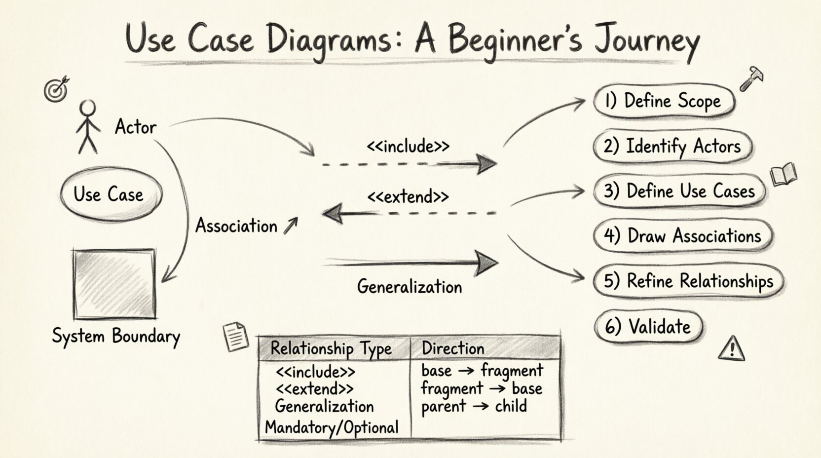
The table below summarizes these relationships for quick reference.
| Relationship Type | Direction | Mandatory or Optional? | Primary Use Case |
|---|---|---|---|
| Include | Base to Fragment | Mandatory | Base Use Case |
| Extend | Fragment to Base | Optional | Base Use Case |
| Generalization | Specialized to Generalized | Inheritance | Generalized Use Case |
Step-by-Step Process for Creation 🛠️
Creating a diagram requires a logical workflow. It is not a drawing exercise but a discovery process. Follow these steps to ensure accuracy.
Step 1: Identify the System Scope
Begin by defining the boundaries. What is the system? What is the context? Write a brief description of the system’s purpose. This prevents the inclusion of external features that belong to other systems.
Step 2: Identify the Actors
Brainstorm every entity that interacts with the system. Ask: Who starts the process? Who receives the output? Who monitors the system? List them all. Group them by role to identify potential generalizations later.
Step 3: Define the Use Cases
For each actor, determine their goals. What do they want to achieve? Write these goals as use cases. Ensure each goal is distinct and complete. Avoid mixing high-level goals with low-level tasks.
Step 4: Draw Associations
Connect actors to use cases. Draw lines between entities that interact. Ensure that every actor has at least one purpose, and every use case has at least one actor.
Step 5: Refine Relationships
Analyze the use cases for commonalities. Can steps be extracted into an include relationship? Are there optional steps that depend on conditions? Use extend or generalization to simplify the diagram.
Step 6: Review and Validate
Walk through the diagram with a stakeholder. Does it match their mental model? Are there missing paths? Is the language clear? Validation is the most critical step in the process.
Practical Example: An Online Library System 📚
To illustrate these concepts, consider an Online Library System. This example demonstrates how to handle different actors and functional requirements.
Actors
- Member: A person who has borrowed books.
- Librarian: Staff who manages the inventory.
- System: Automated notifications and backups.
Use Cases
- Search Catalog: Allows members to find books.
- Borrow Book: Transfers ownership temporarily to the member.
- Return Book: Restores the book to inventory.
- Manage Inventory: Allows the librarian to add or remove books.
- Generate Report: Creates statistics on usage.
Relationships
- Member connects to Search Catalog and Borrow Book.
- Librarian connects to Manage Inventory and Generate Report.
- Borrow Book <<include>> Check Membership Status.
- Borrow Book <<extend>> Apply Fine (if overdue).
This structure ensures that the logic is clear. The “Check Membership Status” is mandatory for borrowing, hence the include. The “Apply Fine” is conditional, hence the extend.
Best Practices for Clarity and Maintainability 📝
A diagram is only as good as its readability. Follow these guidelines to maintain high-quality models.
- Keep It High Level: Do not show every button click. Focus on user goals.
- Use Consistent Naming: If you start with verbs, keep using verbs (e.g., “View,” “Edit,” “Delete”).
- Limit Complexity: If a diagram has more than 15-20 use cases, consider splitting it into subsystems or views.
- Avoid Ambiguity: Do not use lines that cross unnecessarily. Use the “system boundary” to group related functions.
- Document Exceptions: Use the extend relationship to show error handling or optional flows rather than cluttering the main path.
Common Pitfalls and How to Avoid Them ⚠️
Even experienced modelers make mistakes. Recognizing these patterns early can save significant rework.
1. Mixing Levels of Abstraction
A common error is combining high-level goals with low-level steps. For example, “Click Login Button” is a step, not a use case. “Log In” is the use case. Keep the focus on the outcome, not the interaction mechanism.
2. Ignoring the System Boundary
Placing use cases outside the boundary or actors inside it confuses the scope. Remember: Actors are external. Use Cases are internal.
3. Overusing Relationships
Using include or extend relationships for every minor step creates a tangled web. Use them only when there is significant reuse or optional behavior. Simple associations are often sufficient.
4. Neglecting Non-Functional Requirements
Use case diagrams focus on functionality. They do not capture performance, security, or reliability requirements. These must be documented in separate specifications.
Integrating with the Development Lifecycle 🔄
A use case diagram is not a static artifact. It evolves as the project progresses.
- Requirements Phase: Used to gather initial needs and validate scope with clients.
- Design Phase: Helps developers understand the flow of control and data entry points.
- Testing Phase: Serves as a baseline for creating test cases. Each use case should have corresponding test scenarios.
- Maintenance Phase: Updated when new features are added or deprecated features are removed.
By integrating the diagram throughout the lifecycle, teams ensure that the software continues to meet the original intent. It acts as a reference point for change management.
Advanced Considerations for Complex Systems 🧠
For large-scale enterprise systems, a single diagram may not suffice. Consider the following strategies.
Use Case Packages
Group related use cases into packages to organize the diagram logically. This might be based on domain areas (e.g., “Billing,” “User Management,” “Reporting”).
Refinement
High-level use cases can be refined into sub-diagrams. If “Manage Inventory” is too complex, create a detailed diagram specifically for that use case. This is known as use case refinement.
Context Diagrams
Before diving into details, create a context diagram. This shows the system as a single black box interacting with all external entities. It is useful for establishing the high-level ecosystem.
Final Thoughts on System Modeling 🌟
Creating a use case diagram is an exercise in empathy. It requires stepping into the shoes of the user to understand what they value. It is not about drawing shapes; it is about capturing intent.
When done correctly, these diagrams become living documents that guide development and testing. They reduce ambiguity and align teams around a shared vision. Whether you are building a simple application or a complex enterprise platform, the principles remain the same.
Focus on the user. Define the scope clearly. Use relationships to manage complexity. And always validate your work with the people who will use the system. This disciplined approach leads to better software and fewer misunderstandings.
As you continue your journey in systems analysis, remember that tools change, but the need for clear communication remains constant. Mastering the logic behind these diagrams will empower you to design systems that are robust, usable, and aligned with business goals.
Start small. Sketch a diagram for a feature you use daily. Analyze the actors and goals. Practice the relationships. Over time, the patterns will become intuitive, and you will be able to visualize complex systems with confidence.
Happy modeling! 🚀