In the landscape of software engineering, clarity is paramount. As systems grow in complexity, from monolithic structures to distributed microservices, the need for precise visual communication becomes critical. A Use Case Diagram serves as a foundational artifact in this process. It bridges the gap between abstract requirements and concrete technical implementation. This guide explores how these diagrams function within contemporary architectural designs, ensuring that stakeholder expectations align with system capabilities.
Defining the Use Case Diagram 🧩
A Use Case Diagram is a behavioral diagram within the Unified Modeling Language (UML). It depicts the functional requirements of a system. Unlike sequence diagrams that focus on timing and object interaction, this diagram focuses on what the system does from the perspective of an external observer. It acts as a contract between the development team and the business stakeholders.
The primary objective is to visualize the interactions between the system and its environment. By mapping these interactions, architects can identify the scope of the project early in the lifecycle. This prevents scope creep and ensures that development efforts remain focused on delivering specific value propositions.
- Functional Scope: Defines the boundaries of the system.
- Actor Identification: Highlights who or what interacts with the system.
- Goal Visualization: Shows the specific goals users or systems aim to achieve.
Anatomy of a Successful Diagram 📐
Understanding the components is essential for accurate modeling. A well-constructed diagram relies on specific elements that convey meaning without ambiguity. Each element must be used according to established conventions to maintain readability.
1. Actors 👥
Actors represent the roles played by users or external systems. They are drawn as stick figures or icons with labels. It is important to distinguish between different types of actors:
- Human Actors: End users, administrators, or support staff.
- System Actors: Other software applications or hardware devices.
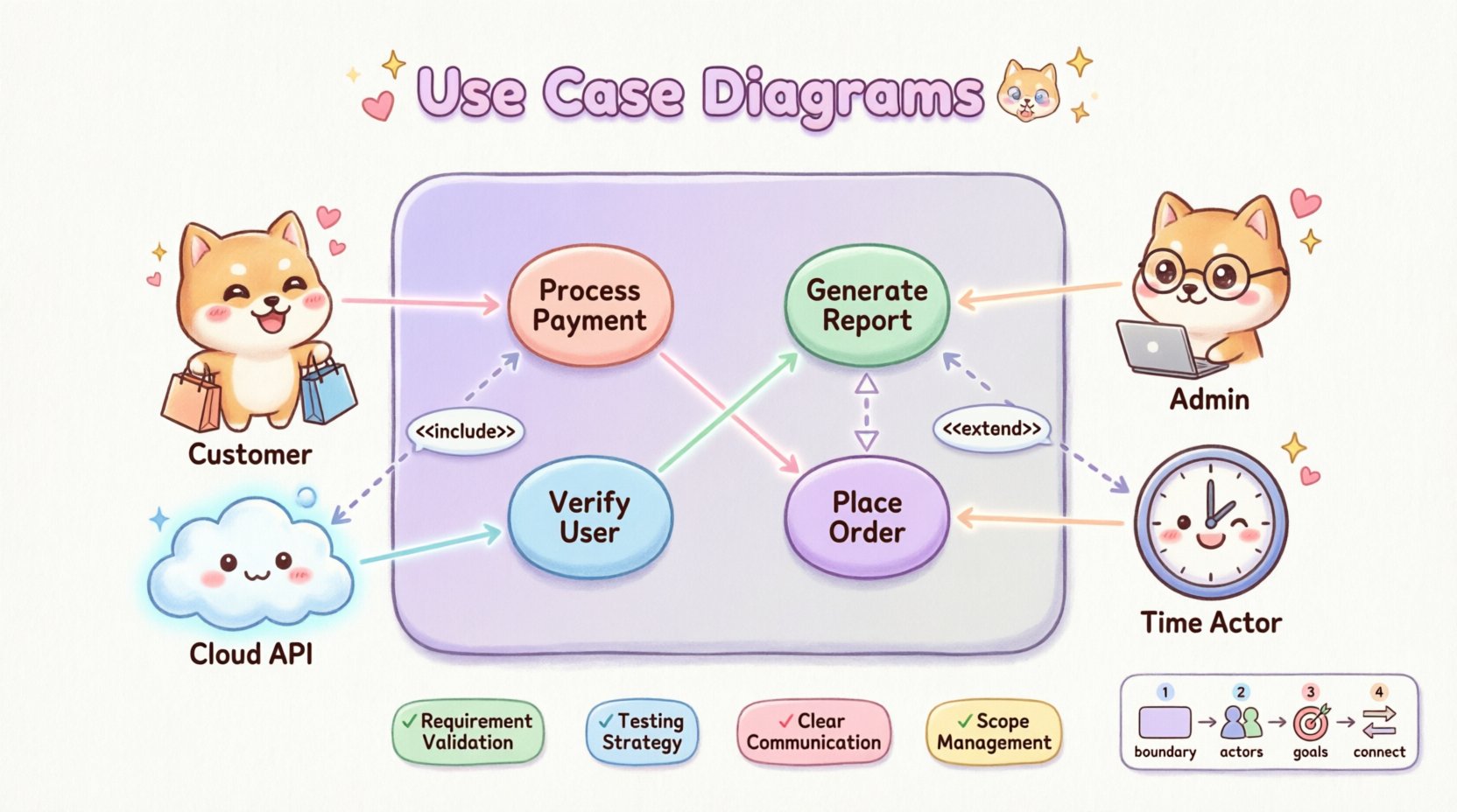
- Time Actors: Scheduled processes that trigger system behavior at specific intervals.
An actor does not describe a specific individual but rather a role. For instance, a “Customer” actor interacts with the system to place orders, regardless of which specific person logs in.
2. Use Cases 🎯
Use Cases are the functional units of the system. They are typically represented as ovals or ellipses. Each oval describes a specific goal or task that the system performs. These should be named using a verb-noun structure, such as “Process Payment” or “Generate Report,” to ensure clarity.
- Atomic Goals: Each use case should represent a single, distinct goal.
- System Boundary: Use cases exist inside the system boundary rectangle.
- Independence: Use cases should ideally be independent of the implementation details.
3. Relationships 🔗
Connections between actors and use cases, or between use cases themselves, define the flow of logic. These relationships are critical for understanding dependencies and system behavior.
Core Relationships Explained 🧠
The power of the diagram lies in how elements connect. There are four primary types of relationships that structure the information.
| Relationship Type | Symbol | Meaning | Example |
|---|---|---|---|
| Association | Line | Direct interaction between actor and use case | Customer places order |
| Include | Dashed arrow with <<include>> | One use case mandates another to function | Login includes Verify Credentials |
| Extend | Dashed arrow with <<extend>> | Optional behavior under specific conditions | Apply Coupon extends Checkout |
| Generalization | Solid line with hollow triangle | Inheritance or specialization of behavior | Admin is a specialized User |
Understanding Include Relationships
An include relationship indicates that a base use case must incorporate another use case to complete its function. This is often used to break down complex processes into reusable components. For example, a “Withdraw Cash” use case might include a “Verify PIN” use case. The verification is not optional; it is a mandatory step for the withdrawal to succeed.
Understanding Extend Relationships
Conversely, an extend relationship represents optional behavior. The extended use case is only executed if specific conditions are met. This allows for flexibility in the design without cluttering the main flow. A “Print Receipt” use case might extend a “Complete Transaction” use case, but only if the user requests a physical copy.
Benefits in Modern Architecture 🚀
Why invest time in creating these diagrams today? The benefits extend beyond simple documentation. They serve as a strategic tool for alignment and risk mitigation.
- Requirement Validation: Stakeholders can verify that the proposed system meets their needs before code is written. This reduces the cost of changes later in the lifecycle.
- Testing Strategy: Each use case can serve as the basis for test cases. QA teams can ensure that every defined function is covered by automated or manual testing protocols.
- Communication Bridge: Technical jargon is minimized. Non-technical stakeholders can understand the system flow without needing to read code or database schemas.
- Scope Management: By defining the boundary, the team can clearly identify what is out of scope. This prevents feature creep during development sprints.
- System Decomposition: In microservices architectures, use cases help identify logical boundaries between services. If a use case relies heavily on specific data, it might indicate a dedicated service.
Integration with Agile and DevOps 🔄
Modern development methodologies often emphasize speed and iteration. Some argue that heavy documentation hinders agility. However, use case diagrams remain valuable when adapted correctly.
Supporting User Stories
In Agile frameworks, use cases can map directly to user stories. While a user story captures a specific perspective (“As a user, I want to…”), the use case diagram provides the visual context of how that story fits into the larger system. This ensures that stories are not isolated but contribute to a cohesive architecture.
Continuous Documentation
In DevOps pipelines, diagrams should not be static artifacts created once and forgotten. They should evolve alongside the code. When a new feature is deployed, the diagram should be updated to reflect the new interactions. This ensures that the documentation remains a source of truth.
Creating a Diagram: A Step-by-Step Approach 📝
Constructing a robust diagram requires a disciplined approach. Rushing through the steps often leads to confusion and inaccurate models.
- Identify the System Boundary: Draw a rectangle that represents the system. Clearly define what is inside and what is outside. This establishes the perimeter for all interactions.
- Define the Actors: List all external entities. Ask questions like, “Who initiates this action?” and “What external systems does this talk to?”
- Map the Goals: Determine what each actor wants to achieve. Write these down as use cases. Ensure they are action-oriented.
- Draw Associations: Connect actors to the use cases they interact with. Use solid lines for direct interactions.
- Refine Relationships: Identify where functionality is shared (Include) or optional (Extend). Add these relationships to reduce redundancy.
- Review and Validate: Walk through the diagram with stakeholders. Verify that all paths make logical sense and that no actor is left without a goal.
Common Pitfalls to Avoid ⚠️
Even experienced architects can make mistakes. Being aware of common errors helps maintain the integrity of the design.
- Overcomplication: Avoid creating diagrams with too many actors or use cases. If a diagram becomes cluttered, it loses its value. Consider splitting a large system into subsystems with separate diagrams.
- Technical Implementation Details: Do not include database tables, API endpoints, or code logic in the diagram. This is a functional model, not a technical design.
- Ignoring Non-Functional Requirements: While the diagram focuses on function, it should not ignore performance or security constraints. Actors like “Security Monitor” should be included if they interact with the system.
- Static Actors: Actors should not change frequently. If you find yourself adding a new actor for every minor change, you may have a boundary issue.
- Missing the “Happy Path”: Focus on the primary success scenario first. Handle error states through Extend relationships or separate diagrams to keep the main flow clear.
Scaling for Microservices and Cloud 🌩️
The rise of microservices has changed how we view system boundaries. In a monolithic architecture, the boundary is clear. In a distributed environment, boundaries can be fluid.
Service Boundaries
When designing microservices, use cases help identify service boundaries. If a set of use cases consistently interact with each other but rarely with others, they likely belong to the same service. This concept aligns with Domain-Driven Design principles.
API Interactions
External systems often interact via APIs. These interactions should be modeled as actors. For example, a “Payment Gateway” is an actor that interacts with the “Process Payment” use case. This makes external dependencies visible and manageable.
Maintaining the Diagram Over Time 📈
A diagram is only useful if it remains accurate. As software evolves, the diagram must evolve with it. This requires a commitment to maintenance.
- Version Control: Store diagrams in the same repository as the code. This ensures that changes to the software trigger updates to the documentation.
- Change Logs: Document why a use case was added or removed. This provides context for future developers.
- Regular Audits: Schedule periodic reviews to ensure the diagram matches the current system state. This is especially important after major releases.
- Tooling: Use modeling tools that support versioning and collaboration. This allows multiple architects to contribute without overwriting work.
Conclusion on Architectural Clarity 🌟
The use case diagram remains a vital tool in the software architecture toolkit. It provides a clear, visual representation of system functionality that transcends technical implementation details. By focusing on interactions and goals, it aligns business needs with technical execution.
While modern architectures introduce new complexities, the fundamental need for clarity remains unchanged. A well-crafted diagram reduces ambiguity, facilitates communication, and serves as a reliable reference throughout the development lifecycle. Whether working on a small application or a large enterprise system, investing time in these diagrams pays dividends in reduced rework and higher quality outcomes.
Adopting this practice ensures that the architecture is not just a collection of code, but a well-understood solution designed to meet specific needs. By adhering to best practices and avoiding common pitfalls, teams can leverage these diagrams to build robust, scalable, and maintainable software systems.