


Creating a clear and effective architecture diagram is essential for managing complex software systems. Among the various diagrams available in the Unified Modeling Language (UML), the Package Diagram stands out as a critical tool for organizing system components. This guide provides a detailed, authoritative walkthrough on constructing these diagrams from the ground up. We will explore the underlying concepts, the specific notation required, and the practical steps to organize your software structure logically.
📚 Understanding the Purpose of Package Diagrams
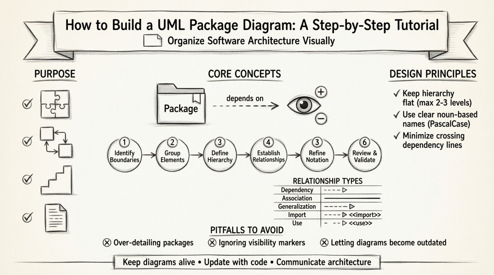
Before drawing lines and boxes, it is necessary to understand why this specific diagram exists. A Package Diagram serves as a high-level view of your system. It does not show individual class methods or detailed logic. Instead, it groups related elements together to manage complexity. Think of it as a table of contents for your software architecture.
When systems grow, the number of classes and interfaces increases. Without organization, developers cannot locate specific functionality. Package diagrams address this by creating namespaces. A namespace allows multiple elements to share the same name without conflict, provided they reside in different packages. This is crucial for large-scale development where teams work on different modules simultaneously.
Key benefits of using this diagram include:
- Modularity: Clearly defined boundaries between different parts of the system.
- Dependency Management: Visualizing how one module relies on another.
- Scalability: Easier to add new features without disrupting existing structures.
- Documentation: Provides a quick reference for stakeholders to understand the system layout.
🔍 Core Concepts and Terminology
To build these diagrams correctly, you must be familiar with the specific vocabulary used in UML standards. The following terms form the foundation of your design.
📦 What is a Package?
A package is a general-purpose mechanism for grouping elements. In the context of software, a package often represents a directory, a module, or a subsystem. It is a container. Inside a package, you can place classes, interfaces, components, and even other packages. This nesting capability allows for hierarchical organization.
🔗 Dependencies
Dependencies represent relationships where one element depends on another for its definition or implementation. If you change the package on the other end of the dependency line, the package on your end might need to change as well. This is a critical concept for understanding coupling.
🏷️ Visibility
While classes have public, private, and protected visibility, packages also have visibility. Elements inside a package can be visible to other packages or hidden. Understanding this helps in designing secure and encapsulated systems.
🛠️ Step-by-Step Guide to Building the Diagram
Follow this structured process to create a robust package diagram. Each step builds upon the previous one to ensure logical consistency.
Step 1: Identify the System Boundaries
Begin by defining what is inside your system and what is outside. The package diagram should focus on the internal structure. Identify the top-level packages that represent the major subsystems of your application. For example, in an e-commerce system, you might have a Orders package, a Inventory package, and a Payment package.
Step 2: Group Related Elements
Review your classes and interfaces. Group them based on their responsibility. If a class handles user authentication, it belongs in an Authentication package. Do not mix data access logic with presentation logic in the same package. Separation of concerns is the guiding principle here.
Step 3: Define the Hierarchy
Determine if you need sub-packages. Large packages can be broken down into smaller, more manageable units. For instance, the Orders package might contain sub-packages for OrderProcessing and OrderHistory. Ensure that the hierarchy is not too deep, as this can make navigation difficult.
Step 4: Establish Relationships
Draw the lines connecting the packages. You are primarily looking for dependencies. Use the standard arrow notation to indicate which package uses another. Be careful to avoid circular dependencies, where Package A depends on Package B, and Package B depends on Package A. This creates a tight coupling that is hard to maintain.
Step 5: Refine Notation
Apply the correct UML notation. Packages are typically represented by a rectangle with a tab at the top left. The package name goes inside the rectangle. Dependencies are shown as dashed arrows. If a package imports another, use a specific stereotype notation.
Step 6: Review and Validate
Walk through the diagram with a peer or a senior architect. Check if every package has a clear purpose. Verify that the dependencies make sense logically. Ensure that the diagram matches the actual code structure or the intended design.
📊 Understanding Relationship Types
Not all lines in a diagram mean the same thing. Using the correct relationship type is vital for accurate communication. The table below outlines the primary relationships used in package diagrams.
| Relationship Type | Notation | Meaning | Usage Example |
|---|---|---|---|
| Dependency | Dashed Arrow | One package uses another. | A user interface package depends on a data access package. |
| Association | Solid Line | Structural connection between packages. | Less common between packages, more for classes. |
| Generalization | Empty Triangle | Inheritance or implementation. | A specialized module extends a base module. |
| Import | Open Arrow with <<import>> | Public elements are visible. | Accessing shared utility classes. |
| Use / Extend | Dashed Arrow with <<use>> | Extension points. | Optional features added to a core system. |
🎨 Design Principles for Clarity
A diagram is useless if it is confusing. Adhering to design principles ensures that the visual output conveys the intended information clearly.
📏 Keep it Flat
Avoid creating deep hierarchies. If you find yourself nesting packages more than three levels deep, reconsider your grouping strategy. Deep nesting makes it difficult to see the overall system flow. Aim for a two-level structure: Top-level subsystems and specific functional modules.
🏷️ Naming Conventions
Names should be consistent and meaningful. Use nouns for packages (e.g., Reporting) rather than verbs (e.g., GenerateReports). This aligns with the concept of a container. Avoid abbreviations unless they are industry standard. Consistent capitalization (PascalCase or camelCase) helps in reading the diagram quickly.
🚫 Minimize Crossing Lines
Crossing dependency lines create visual noise. Arrange packages spatially to minimize intersections. If lines must cross, consider using a bridge or a separate layer to indicate the connection, though in standard package diagrams, simple layout adjustments are usually sufficient.
🔌 Managing Dependencies and Imports
Dependencies are the lifeblood of package diagrams, but they can also be the source of fragility. Understanding how to manage them is a key skill.
📥 The Import Mechanism
When one package needs to use a public class from another, an import relationship is established. This is not a dependency in the execution sense, but a compilation or visibility sense. It indicates that the classes are available to be referenced. Use the <<import>> stereotype to denote this explicitly.
🔗 The Use Relationship
Dependencies often represent the <<use>> relationship. This implies that the client package requires the supplier package to function. If the supplier package changes its interface, the client package must adapt. This is a strong indicator of coupling.
🔄 Avoiding Circular Dependencies
Circular dependencies occur when Package A imports Package B, and Package B imports Package A. This creates a cycle that can lead to initialization errors and make the system hard to test. To resolve this:
- Extract the shared interface into a third package.
- Refactor the code so that one package does not depend on the other.
- Use dependency injection to break the direct link.
🚨 Common Pitfalls to Avoid
Even experienced practitioners can make mistakes when constructing these diagrams. Being aware of common errors helps you avoid them.
❌ Over-Detailing
A common mistake is to include too much detail. Do not list every class inside a package. If a package contains fifty classes, the diagram becomes cluttered. Instead, show the package as a single unit and provide a separate class diagram for the internal details. The package diagram is for the overview, not the granular implementation.
❌ Ignoring Package Visibility
Not all elements inside a package should be visible to the outside world. If you expose internal implementation details, you lock developers into a specific implementation. Use visibility markers to indicate which parts are public and which are private. This enforces encapsulation at the architectural level.
❌ Static Diagrams
Do not treat the diagram as a one-time task. As the software evolves, the structure changes. If you do not update the diagram, it becomes a lie. It is better to have a diagram that is 90% accurate and updated regularly than a perfect diagram that is never touched again.
🔄 Maintenance and Evolution
Software is dynamic. The structure of the system changes over time. Your diagrams must reflect these changes.
📝 Synchronization
Whenever a new module is added or a major refactor occurs, review the package diagram. Ensure that the new dependencies are drawn and the old ones are removed. In some environments, tools can generate these diagrams from the source code. While manual creation offers more control, automated generation ensures accuracy.
📢 Communication
Use the diagram to communicate with the team. During sprint planning or architecture reviews, the package diagram is a valuable artifact. It helps everyone understand where their work fits into the larger picture. If a developer is adding a feature to the Reporting module, they can look at the diagram to see which other modules they might impact.
🧩 Advanced Usage Scenarios
Once you are comfortable with the basics, you can apply these concepts to more complex scenarios.
🌐 Distributed Systems
In distributed architectures, packages might represent microservices or distinct deployment units. The dependencies here often represent network calls or API interactions rather than direct method calls. The diagram helps visualize the data flow between services.
🔒 Security Boundaries
You can use packages to define security zones. For example, a PublicAPI package might be accessible from the internet, while a InternalCore package is restricted to the local network. Marking these boundaries clearly in the diagram helps security teams audit the system.
🧪 Testing Strategies
Package structures often dictate testing strategies. Integration tests might be run across package boundaries, while unit tests stay within a single package. Understanding the dependencies helps in isolating tests and mocking external packages effectively.
📝 Final Considerations
Building a UML Package Diagram is an exercise in organization and clarity. It requires a deep understanding of how the components of your system interact. By following the steps outlined above, you create a map that guides development and maintenance. Remember that the goal is not perfection, but understanding. A diagram that helps the team make better decisions is a successful diagram.
Focus on the relationships and the structure. Keep the notation standard. Respect the boundaries. And keep the diagram alive as the system grows. This approach ensures that your architecture remains coherent and manageable throughout the lifecycle of the project.