


Software architecture relies on clear communication. As systems grow in complexity, visualizing the high-level organization of code becomes essential. The UML Package Diagram serves this purpose perfectly. It provides a structural view of the system, showing how different modules relate to one another without getting bogged down in implementation details. This guide walks you through the process of creating one, ensuring you understand the core concepts and practical steps involved.
Understanding the Package Concept 📦
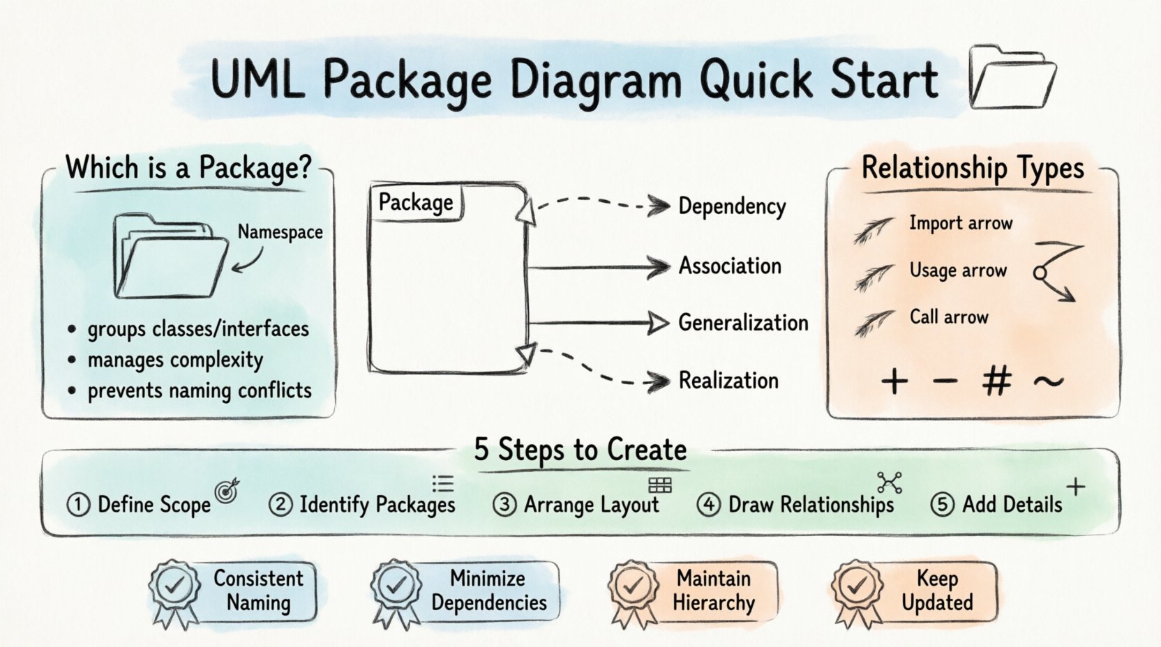
Before you begin drawing, it is crucial to understand what a package represents in Unified Modeling Language (UML). A package is a namespace that organizes a set of related elements. Think of it as a folder on your computer that holds related files. In software architecture, these elements are typically classes, interfaces, subsystems, or even other packages.
Why use packages? They help manage complexity. Instead of viewing thousands of classes at once, you group them into logical units. This abstraction allows developers to focus on specific areas of the system while understanding the boundaries of their work.
Key Characteristics of Packages
- Namespace Management: Packages prevent naming conflicts. A class named
Userin one package does not conflict with a class namedUserin another. - Logical Grouping: They group elements based on functionality, responsibility, or subsystem.
- Visibility Control: Packages define which elements are accessible to other parts of the system and which remain private.
- Dependency Handling: They show how modules depend on one another, which is critical for understanding system coupling.
Core Symbols and Notation 🎨
UML is a language with specific rules. To create a valid diagram, you must adhere to standard notations. While tools vary, the visual representation of packages remains consistent across the industry.
Visual Representation
A package is typically depicted as a rectangle with a tab at the top left corner. The name of the package is written inside the tab. If the package contains elements, they are listed inside the main body of the rectangle.
Common Symbols Table
| Symbol | Meaning | Visual Description |
|---|---|---|
| Package | Namespace for grouping elements | Rectangle with a top-left tab |
| Dependency | One element uses another | Dashed arrow with open arrowhead |
| Association | Structural relationship between elements | Solid line |
| Generalization | Inheritance relationship | Solid line with a hollow triangle |
| Realization | Implementation of an interface | Dashed line with a hollow triangle |
Relationships and Dependencies 🔗
The true power of a package diagram lies in the connections between packages. These connections describe how the system is constructed and how changes in one area might affect others.
Dependency Relationships
A dependency exists when a change in one element requires a change in another. In package diagrams, this is often the most common relationship. It indicates that one package needs to know about the interface of another to function correctly.
- Import: A package explicitly imports elements from another, making them available in its namespace.
- Usage: One package uses an operation or attribute from another without necessarily importing it.
- Call: A package invokes a service provided by another package.
Visibility and Access
Understanding visibility is key to maintaining a healthy architecture. Packages can restrict access to their internal elements.
- + Public: Visible to all other packages.
- – Private: Visible only within the same package.
- # Protected: Visible within the package and by derived packages.
- ~ Package: Visible only to other packages within the same namespace.
When drawing lines between packages, use the appropriate arrowhead and line style to denote the type of relationship. A dashed line with an open arrowhead is the standard for dependencies.
Step-by-Step Guide to Creation 🛠️
Creating a diagram requires a systematic approach. Follow these steps to ensure your model is accurate and useful.
1. Define the Scope
Before opening the modeling interface, determine what you are modeling. Is it the entire system, a specific subsystem, or a new feature? A diagram that tries to show everything becomes unreadable. Focus on the relevant boundaries.
- Identify the top-level modules.
- Determine the level of detail required.
- Decide which diagrams this package diagram will complement.
2. Identify Packages
List the logical groupings of your system. These should represent major functional areas.
- Core Logic: The business rules and processing engine.
- Data Access: Database interactions and storage.
- Interface: User-facing components or API endpoints.
- Utilities: Shared helper functions and tools.
3. Arrange the Layout
Place the packages on the canvas. Group related packages together spatially to reflect their logical proximity. Use alignment tools to keep lines straight and readable.
- Place the most central or core packages in the middle.
- Position dependent packages near the packages they rely on.
- Use layers if the system has a clear hierarchy (e.g., Presentation, Business, Data).
4. Draw Relationships
Connect the packages using the appropriate symbols. Be precise. A dependency should point from the client (the one using) to the supplier (the one being used).
- Select the dependency tool.
- Click on the source package.
- Drag to the target package.
- Label the relationship if necessary (e.g., “uses”, “depends on”).
5. Add Internal Structure (Optional)
If the package diagram needs to show more detail, you can include elements inside the package rectangles. List the classes or interfaces contained within.
- Use indentation to show hierarchy.
- Keep the list concise to avoid clutter.
- Focus on public interfaces rather than private implementation details.
Best Practices for Clean Modeling 📝
A well-drawn diagram communicates effectively. A messy one confuses the audience. Adhere to these guidelines to maintain quality.
1. Consistent Naming Conventions
Naming is the first point of contact for readers. Use clear, descriptive names for packages and elements.
- Avoid single-letter names like
A,B, orX. - Use camelCase or PascalCase consistently.
- Ensure the name reflects the content (e.g.,
PaymentProcessinginstead ofCore). - Use nouns for packages and verbs for actions if labeling relationships.
2. Minimize Cross-Package Dependencies
High coupling makes systems hard to maintain. Aim for low coupling between packages.
- Reduce the number of arrows pointing between distant packages.
- Introduce an interface layer if a dependency is too deep.
- Review circular dependencies carefully; they often indicate a design flaw.
3. Maintain Hierarchy
Do not mix levels of abstraction. If a package contains sub-packages, ensure the relationship is clear.
- Use nesting for sub-packages.
- Ensure parent packages represent the aggregate of their children.
- Do not show the same element in multiple top-level packages unless necessary for clarity.
4. Regular Updates
A diagram that does not match the code is worse than no diagram. Keep it synchronized.
- Update the diagram when code is refactored.
- Review the diagram during design sprints.
- Archive old versions if the system has evolved significantly.
Common Mistakes to Avoid ⚠️
Even experienced modelers make errors. Being aware of common pitfalls saves time and prevents confusion.
1. Over-Detailing
One of the most frequent errors is trying to show too much detail in a package diagram. This turns a high-level view into a class diagram.
- Do not list every single attribute or method.
- Focus on the package boundaries, not internal implementation.
- If you need to show class details, create a separate Class Diagram.
2. Inconsistent Relationships
Using different line styles for the same type of relationship creates ambiguity.
- Always use dashed lines for dependencies.
- Always use solid lines for associations.
- Ensure arrowheads are consistent (open for dependency, filled for association).
3. Ignoring Directionality
Dependencies are directional. A package depends on another, not the other way around.
- Check that the arrow points from the client to the supplier.
- Reversing an arrow changes the meaning entirely.
- Label bidirectional relationships clearly if they exist.
4. Floating Elements
Elements should not float without context. Every element should belong to a package or be clearly defined as part of a subsystem.
- Ensure all classes are assigned to a package.
- Group related elements together.
- Use packages to organize, not just to hold elements.
When to Use Package Diagrams 🕒
Not every situation requires a package diagram. Use them strategically based on the project phase and needs.
System Design Phase
This is the primary use case. When designing the architecture, package diagrams help stakeholders understand the module structure before writing code.
Documentation
They serve as excellent documentation for new team members. A clear package structure helps developers find where specific functionality resides.
Refactoring
When cleaning up legacy code, a package diagram helps visualize the current state and plan the restructuring.
Integration Planning
When integrating third-party libraries or services, package diagrams show where the external dependencies enter the system.
Integrating with Other Diagrams 🔗
Package diagrams do not exist in isolation. They work in tandem with other UML diagrams to provide a complete picture of the system.
Class Diagrams
Package diagrams define the boundaries, while Class Diagrams define the content within those boundaries. Use the package diagram to locate the relevant Class Diagram.
Component Diagrams
Component diagrams are similar but focus on executable units. Package diagrams are more abstract. Use packages for logical organization and components for physical deployment.
Sequence Diagrams
Sequence diagrams show interactions over time. Package diagrams provide the static context for these interactions. Knowing which package an object belongs to helps trace its origin.
Maintenance and Evolution 🔄
Software evolves. A package diagram is a living document. It must evolve with the codebase.
Version Control
Store your diagram files alongside your code in the version control system. This ensures that changes to the architecture are tracked.
- Commit changes when refactoring occurs.
- Document the reason for structural changes in commit messages.
- Review the diagram during code reviews.
Automation
Some modeling tools can generate diagrams from code. While manual drawing offers better control, automated generation ensures accuracy.
- Use tools that support reverse engineering.
- Verify generated diagrams against the actual code.
- Do not rely solely on automation for architectural decisions.
Summary of Key Takeaways 📌
- Organization: Packages group related elements to manage complexity.
- Dependencies: Use dashed arrows to show how packages rely on each other.
- Clarity: Keep the diagram high-level; avoid excessive detail.
- Consistency: Follow naming conventions and standard notation rules.
- Maintenance: Update the diagram as the system changes.
Creating a UML Package Diagram is a foundational skill for any software architect. It bridges the gap between abstract requirements and concrete implementation. By following the steps and best practices outlined above, you can produce clear, effective diagrams that enhance understanding and communication within your team. Start with a simple structure, refine your relationships, and let the diagram guide your development process.