


Enterprise software architecture is inherently complex. As systems grow in functionality and user base, the underlying structure must remain maintainable, scalable, and understandable. At the heart of this structural integrity lies the Unified Modeling Language (UML) Package Diagram. While often overshadowed by class or sequence diagrams in smaller contexts, the package diagram provides the essential high-level view required to manage large-scale systems. This guide explores the principles, strategies, and best practices for scaling UML package diagrams effectively within enterprise environments.
When dealing with distributed teams, microservices, or monolithic systems that evolve over decades, a static map of the codebase is insufficient. A dynamic, logical model is necessary to communicate intent, boundaries, and interactions. This document details how to construct and maintain these models without relying on specific vendor tools, focusing instead on universal architectural patterns.
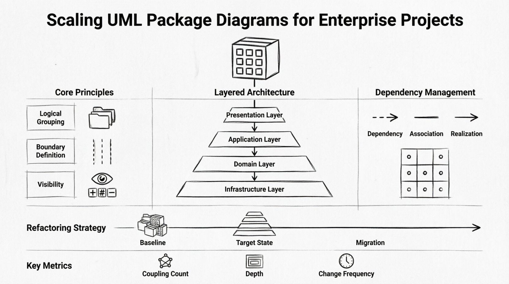
📦 Understanding Package Diagrams at Scale
A package in UML is a mechanism for organizing elements into groups. In a small project, a package might represent a single module. In an enterprise context, a package represents a distinct domain, a layer, or a subsystem. The goal is to reduce cognitive load by hiding implementation details behind clear interfaces.
When scaling, the distinction between logical packages and physical deployment becomes critical. The diagram should reflect the logical architecture, not necessarily the folder structure on a disk. This separation allows teams to refactor code without constantly updating the architectural model.
- Logical Grouping: Group components by responsibility, such as data access, business logic, or presentation.
- Boundary Definition: Clearly mark where one package ends and another begins to define ownership.
- Visibility: Use standard visibility modifiers (public, private, protected) to control access between packages.
Without clear boundaries, the diagram becomes a “spaghetti” representation where everything connects to everything else. Scalability requires strict adherence to layering and separation of concerns.
🏛️ Architectural Principles for Large Systems
Successful scaling relies on established architectural principles. Applying these to package diagrams ensures that the visual representation matches the operational reality of the software.
1. Layered Architecture
Most enterprise systems follow a layered approach. Each layer has a specific responsibility and should only interact with the layer immediately below it. This minimizes coupling and allows for independent testing and deployment.
- Presentation Layer: Handles user interface and user experience.
- Application Layer: Orchestrates business processes and workflows.
- Domain Layer: Contains the core business rules and entities.
- Infrastructure Layer: Manages data persistence, messaging, and external services.
2. Domain-Driven Design (DDD)
In complex domains, packages should align with Bounded Contexts. A Bounded Context is a linguistic boundary within which a specific domain model is defined and applicable. Aligning packages with Bounded Contexts ensures that the diagram reflects the business language and constraints.
3. Modularity
Modules are self-contained units that can be developed, tested, and deployed independently. In a package diagram, modularity is visualized through clear interfaces and dependencies. A well-designed package allows for hot-swapping of implementations without breaking the system.
📝 Naming Conventions and Organization
Consistency is the backbone of maintainability. When multiple teams contribute to the same model, naming conventions prevent confusion and merge conflicts. A standardized approach to naming packages ensures that any stakeholder can navigate the architecture without prior knowledge.
- Namespace Prefixes: Use prefixes to denote the layer or domain (e.g.,
com.enterprise.core,com.enterprise.ui). - Descriptive Labels: Avoid abbreviations unless they are industry standard. The name should describe the function, not just the technology.
- Versioning: Include version indicators for packages that are deprecated or in transition.
Consider the following naming structure for a financial system:
com.finance.accounting– Core business logic for accounting.com.finance.reporting– Logic for generating reports.com.finance.integration– External data feeds and APIs.
Consistent naming reduces the cognitive overhead when onboarding new developers. It also aids in automated code generation and documentation processes.
🔗 Managing Dependencies and Coupling
Dependency management is the most critical aspect of scaling package diagrams. High coupling leads to fragile systems where a change in one area causes unintended side effects elsewhere. The diagram must explicitly show how packages relate to one another.
There are three primary types of relationships to manage:
- Dependency: One package uses another. This is a “uses-a” relationship.
- Association: A structural link between instances of packages.
- Realization: One package implements an interface defined by another.
To maintain health, minimize the number of incoming dependencies. A package should depend on abstractions, not concrete implementations. This is achieved through interface segregation.
Dependency Matrix
Use a matrix to track dependencies during the design phase. This helps identify circular dependencies before code is written.
| Package A | Package B | Package C | Impact |
|---|---|---|---|
| ✓ | – | – | Package A depends on B. |
| – | ✓ | – | Package B depends on C. |
| – | – | ✓ | Package C is independent. |
| ? | ? | ? | Review for circularity. |
When analyzing the diagram, look for cycles. A cycle between Package A and Package B indicates a tight coupling that needs refactoring. Introduce an interface package to break the cycle.
🔄 Incremental Refactoring Strategies
Legacy systems rarely start with perfect architecture. Refactoring a package diagram is an iterative process. You cannot rewrite the entire model overnight. The strategy must be incremental and risk-managed.
Step 1: Baseline the Current State
Create a diagram that accurately reflects the current system, even if it is messy. This serves as the source of truth. Identify the critical paths and high-risk areas.
Step 2: Define the Target State
Design the ideal package structure. This should align with the desired future architecture. Ensure that the target state supports the business goals, not just technical preferences.
Step 3: Plan the Migration
Map the old packages to the new ones. Identify which classes need to move and which interfaces need to be created. Execute the migration in small batches, verifying the system after each step.
- Shadowing: Create new packages alongside old ones. Route new traffic to the new packages.
- Strangler Fig: Gradually replace functionality piece by piece until the old system is obsolete.
- Interface Contracts: Define contracts early to ensure compatibility during the transition.
👥 Collaboration Across Distributed Teams
In large enterprises, multiple teams work on different parts of the same system. The package diagram must serve as a contract between these teams. It defines what one team exposes and what another team consumes.
Ownership Models
Define clear ownership for each package. A package owner is responsible for the stability of the interface and the documentation of changes. This prevents “tragedy of the commons” where everyone modifies the same area.
Review Processes
Establish a review process for package diagram changes. This ensures that new dependencies do not violate architectural standards. A simple checklist can be used during pull requests:
- Does the new dependency violate the layering rule?
- Is the naming convention consistent?
- Has the interface been updated to reflect the change?
- Are there any circular dependencies introduced?
⚠️ Common Pitfalls and How to Avoid Them
Even experienced architects make mistakes when scaling diagrams. Recognizing these pitfalls early can save months of rework.
1. Over-Abstraction
Creating too many levels of indirection can make the system hard to navigate. If you have five layers of wrapper packages, the intent is lost. Keep the hierarchy shallow and meaningful.
2. Ignoring Physical Deployment
A logical diagram that does not align with deployment topology can lead to network bottlenecks. Ensure that packages that interact frequently are deployed close to each other to reduce latency.
3. Static Documentation
A diagram that is not updated becomes a liability. If the code changes and the diagram does not, developers will stop trusting the model. Integrate diagram updates into the development workflow.
4. Tool Dependency
Do not tie the model to a specific tool’s proprietary format. Use standard UML notation that can be exported or converted. This ensures long-term accessibility of the architectural knowledge.
📚 Integrating with Documentation Systems
The package diagram should not exist in isolation. It is part of a larger documentation ecosystem. Integrating the diagram with technical specifications, API documentation, and deployment guides provides a complete view of the system.
- API Contracts: Link package interfaces to API specifications (e.g., OpenAPI).
- Deployment Guides: Reference package boundaries in deployment scripts.
- Onboarding: Use the diagram as the primary visual aid for new hires.
This integration ensures that the architectural intent is preserved throughout the software development lifecycle.
📊 Monitoring Model Health over Time
Just as code requires monitoring, the model requires health checks. Over time, drift occurs between the diagram and the code. Automated metrics can help detect this drift.
Key Metrics
- Coupling Count: Number of dependencies per package. High counts indicate refactoring needs.
- Depth of Hierarchy: Number of nested packages. Deep hierarchies increase navigation time.
- Change Frequency: How often a package is modified. High frequency may indicate instability.
Regular audits of these metrics allow the team to proactively address architectural debt. A package that changes frequently should be reviewed for stability.
🔮 Future Proofing and Evolution
Technology evolves, and so must the architecture. The package diagram should be flexible enough to accommodate new requirements without requiring a complete rewrite. Design for extension, not just implementation.
Consider the following strategies for future readiness:
- Plugin Architecture: Design packages that can accept external plugins or modules.
- Feature Flags: Use package boundaries to isolate new features behind flags.
- Cloud Readiness: Structure packages to support cloud-native deployment patterns like containers and serverless functions.
By focusing on modularity and clear interfaces, the system can adapt to new technologies without breaking existing functionality. The diagram serves as the blueprint for this evolution.
🛠️ Final Considerations
Scaling UML package diagrams is not merely a documentation exercise; it is a strategic activity that influences the entire software development lifecycle. It requires discipline, consistency, and a deep understanding of the system’s domain.
Success depends on treating the diagram as a living artifact that evolves with the code. It must be accurate, accessible, and relevant to the teams building the system. By following the principles outlined in this guide, organizations can achieve a level of architectural clarity that supports long-term growth and stability.
Remember that the goal is not perfection, but progress. Start with a clear structure, enforce naming conventions, manage dependencies rigorously, and review the model regularly. With these practices in place, the package diagram becomes a powerful tool for communication and control in any enterprise project.