


Modern software architecture relies on the ability to organize complex systems into manageable, distinct units. As applications grow in size and functionality, the risk of tangled dependencies and unclear boundaries increases significantly. A well-structured architecture ensures maintainability, scalability, and testability. One of the most effective tools for visualizing these structural relationships is the UML Package Diagram. This guide explores how to use package diagrams to isolate modules effectively, ensuring your system remains robust over time.
🔍 Understanding UML Package Diagrams
A UML Package Diagram is a type of structural diagram that organizes elements into groups. These groups are called packages. Unlike class diagrams, which focus on individual classes and their attributes, package diagrams operate at a higher level of abstraction. They define namespaces and boundaries for logical groupings of components.
- Namespace Management: Packages help resolve naming conflicts by providing a hierarchical structure.
- Logical Grouping: They allow developers to group related classes, interfaces, and subsystems together.
- Visibility Control: Packages define the scope of visibility for elements contained within them.
When used correctly, these diagrams act as a blueprint for the system’s skeleton. They do not describe behavior in detail but rather the static structure and how different parts of the system relate to one another. This distinction is vital for architectural planning.
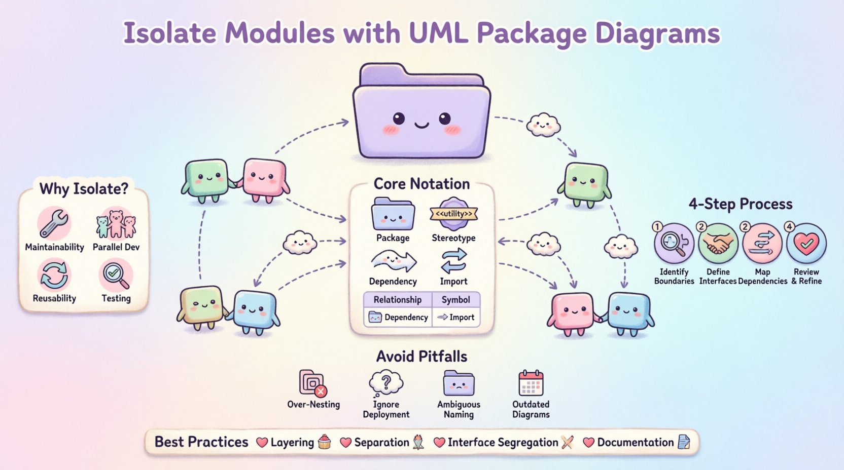
🧩 Why Module Isolation Matters
Module isolation is the practice of ensuring that a specific part of a software system operates independently of others as much as possible. This concept is often tied to the principles of High Cohesion and Low Coupling.
High cohesion means that the elements within a package are closely related and work together to perform a specific task. Low coupling means that changes in one package have minimal impact on other packages. Achieving this balance reduces the ripple effect of bugs and simplifies debugging.
Benefits of Effective Isolation
- Maintainability: Developers can modify one module without fear of breaking unrelated functionality.
- Parallel Development: Teams can work on different packages simultaneously with reduced merge conflicts.
- Reusability: Isolated modules are easier to extract and use in other projects.
- Testing: Unit testing becomes more straightforward when dependencies are clearly defined and limited.
Without isolation, systems become fragile. A change in a utility function could cascade through the entire codebase. Package diagrams provide the visual evidence needed to enforce these boundaries.
📐 Core Concepts of UML Package Notation
To isolate modules effectively, you must understand the standard notation used in UML. The syntax is standardized by the Object Management Group (OMG). Using the correct symbols ensures that all stakeholders, from developers to architects, share a common understanding.
Here are the essential elements you will encounter:
- Package Symbol: Represented by a folder icon or a rectangle with a tab at the top left. It contains the package name.
- Package Stereotype: Text enclosed in guillemets (e.g., <<utility>>) indicates the type or role of the package.
- Dependency: A dashed arrow indicating that one package requires another to function.
- Import: Indicates that a package makes all elements of another package visible within its namespace.
- Access: Similar to import but allows direct access to specific elements.
Relationship Types Table
| Relationship | Symbol | Meaning |
|---|---|---|
| Dependency | Dashed Arrow | Usage relationship; change in source may affect target. |
| Association | Solid Line | Structural relationship; instances of one package relate to another. |
| Import | Dashed Arrow with Double Arrowhead | Imports namespace; elements become visible without qualification. |
| Realization | Dashed Arrow with Hollow Triangle | One package implements the interface of another. |
Understanding these symbols is the first step toward creating clear diagrams. Misinterpreting a dependency as an association can lead to architectural confusion.
🛠️ Step-by-Step Guide to Isolating Modules
Creating a package diagram is not just about drawing boxes. It requires a deliberate process of analyzing the system and defining boundaries. Follow these steps to ensure your modules are isolated correctly.
1. Identify Functional Boundaries
Begin by analyzing the requirements and the domain model. Group functionalities that belong together. For example, a billing system might have distinct packages for Invoice Generation, Payment Processing, and Reporting. Each of these should ideally be separate packages.
- Look for common verbs and nouns in the domain.
- Separate business logic from technical infrastructure.
- Keep user interface elements distinct from data access logic.
2. Define Interfaces Between Packages
Once boundaries are set, define how they interact. Modules should not know about the internal implementation of other modules. Instead, they should interact through defined interfaces.
- Create an interface package that lists the contracts between modules.
- Use dependency arrows to show which package depends on which interface.
- Avoid direct access to internal classes of other packages.
3. Map Dependencies Explicitly
Draw the connections between your packages. Ensure that dependencies flow in one direction whenever possible. Cyclic dependencies are a major sign of poor isolation.
- Map the flow of data and control between packages.
- Label the arrows with the type of relationship (e.g., uses, implements).
- Verify that no two packages depend on each other directly.
4. Review and Refine
After the initial draft, review the diagram with the development team. Ask questions about the boundaries. Are there packages that are too large? Are there dependencies that seem unnecessary?
- Check for packages that contain unrelated functionality.
- Ensure naming conventions are consistent across all packages.
- Validate that the diagram matches the actual code structure.
🔗 Managing Dependencies and Coupling
Dependencies are the lifeblood of software systems, but they are also the source of complexity. Managing them requires discipline. The goal is to reduce coupling to the point where modules can be swapped or updated independently.
Types of Coupling
Different types of coupling exist, ranging from acceptable to problematic. Understanding these helps in designing better package structures.
- Data Coupling: Modules share data through parameters. This is generally acceptable and preferred.
- Control Coupling: One module controls the flow of another. Use sparingly.
- Common Coupling: Multiple modules share a global data area. This creates hidden dependencies.
- Content Coupling: One module modifies the internal logic of another. This should be avoided.
Handling Cyclic Dependencies
Cyclic dependencies occur when Package A depends on Package B, and Package B depends on Package A. This creates a circular chain that makes isolation impossible. To resolve this:
- Extract the shared logic into a new, third package.
- Introduce an interface that both packages implement.
- Refactor the design so that one package becomes a consumer of the other, not a peer.
Package diagrams make these cycles visible. If you see a loop in your diagram, it is a signal to refactor the architecture.
⚠️ Common Pitfalls and Solutions
Even experienced architects make mistakes when designing package structures. Being aware of common pitfalls helps you avoid them.
Pitfall 1: Over-Nesting Packages
Creating too many levels of nested packages can make the system harder to navigate. A deep hierarchy obscures relationships.
- Solution: Limit nesting to two or three levels deep.
- Solution: Use flat structures where possible for related components.
Pitfall 2: Ignoring Physical Deployment
Logical packages do not always match physical deployment units. A package might span multiple servers or databases.
- Solution: Document the deployment topology separately from the package diagram.
- Solution: Use stereotypes to indicate physical constraints.
Pitfall 3: Ambiguous Naming
Package names should be descriptive. Generic names like Utils or Core often become dumping grounds for unrelated code.
- Solution: Use domain-specific names (e.g., PaymentGateway instead of Services).
- Solution: Define a naming convention for the project.
Pitfall 4: Outdated Diagrams
A package diagram that does not match the code is worse than no diagram at all. It creates false confidence.
- Solution: Treat the diagram as code that must be updated with every change.
- Solution: Integrate diagram updates into the code review process.
📋 Best Practices for Scalability
As your system grows, the package structure must evolve. Scalability is not just about performance; it is about the ability to add features without restructuring the entire architecture.
- Layering: Organize packages into layers such as Presentation, Business Logic, and Data Access. This enforces a clear flow of information.
- Separation of Concerns: Ensure that each package has a single responsibility. If a package does two things, split it.
- Interface Segregation: Do not force a package to depend on an interface it does not use. Create specific interfaces for specific needs.
- Documentation: Add descriptions to packages. Explain the intent of the package, not just its contents.
🔄 Integrating Package Diagrams into Workflow
Creating a diagram is one thing; using it effectively is another. The diagram should be a living document that guides development.
- Design Phase: Use the diagram to plan the architecture before writing code.
- Development Phase: Refer to the diagram to understand where new code belongs.
- Review Phase: Check pull requests against the diagram to ensure no boundaries are crossed.
- Onboarding: Use the diagram to help new developers understand the system structure quickly.
This integration ensures that the diagram remains relevant. It becomes a tool for communication rather than just a static artifact.
🏁 Summary of Module Isolation
Isolating modules using UML Package Diagrams is a strategic approach to managing complexity. It requires a clear understanding of dependencies, a disciplined approach to naming, and a commitment to keeping the documentation in sync with the code. By following these guidelines, you create a system that is easier to understand, modify, and extend.
Focus on the relationships between packages as much as the packages themselves. A well-drawn package diagram is a map that guides the entire development team through the complexity of the software landscape. It clarifies boundaries, defines contracts, and prevents the architectural decay that often plagues large systems.
Remember that the goal is not perfection on the first attempt. It is about establishing a structure that can be refined over time. Start with clear boundaries, define your interfaces, and manage your dependencies carefully. This foundation will support your software as it grows.