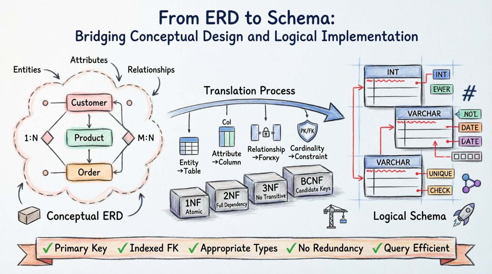
Database architecture begins with a vision. Before a single line of code is written, data structures must be conceptualized, organized, and validated. The Entity-Relationship Diagram (ERD) serves as the blueprint for this structure, translating real-world requirements into a visual model. However, a diagram alone does not store data. The logical schema is the tangible implementation that governs how information is physically stored, retrieved, and secured.
Transitioning from the abstract ERD to the concrete schema requires precision. It involves mapping entities to tables, relationships to keys, and attributes to columns. This process dictates the integrity and performance of the entire system. Understanding the nuances of this translation ensures that the database remains robust under load and adaptable to future needs.
Understanding the Conceptual Foundation 🧱
The Entity-Relationship Diagram operates at the conceptual level. It focuses on the “what” rather than the “how.” In this phase, stakeholders and architects identify the core objects of interest within the domain.
- Entities: These represent distinct objects or concepts, such as a Customer, Product, or Order.
- Attributes: These define the properties of an entity, like a Name, Price, or Date.
- Relationships: These describe how entities interact, such as a Customer placing an Order.
At this stage, technical constraints are secondary. The goal is clarity. If the conceptual model is ambiguous, the resulting schema will be flawed. Common mistakes include conflating attributes with entities or failing to define cardinality correctly.
Cardinality and Participation
One of the most critical aspects of ERD design is defining cardinality. This dictates the quantitative relationship between entities.
- One-to-One (1:1): A single record in Table A relates to exactly one record in Table B.
- One-to-Many (1:N): A single record in Table A relates to multiple records in Table B.
- Many-to-Many (M:N): Multiple records in Table A relate to multiple records in Table B.
Participation constraints further refine this model. Is the relationship mandatory or optional? If a Customer must place an Order, the participation is mandatory. If they can exist without an Order, it is optional. These distinctions directly influence the nullability of columns in the logical schema.
The Logical Schema: Structural Implementation 🏗️
The logical schema bridges the gap between theory and physical storage. While the ERD is platform-independent, the logical schema prepares the data for specific storage mechanisms. This layer introduces specific rules regarding data types, constraints, and normalization.
Unlike the conceptual model, the logical schema must address data integrity explicitly. This is achieved through primary keys, foreign keys, and unique constraints. These rules prevent orphaned records and ensure that relationships remain consistent.
Key Translation Rules
Translating keys from ERD to Schema requires strict adherence to relational theory.
- Primary Keys: Every entity must have a unique identifier. In the ERD, this is often underlined. In the schema, it becomes the PRIMARY KEY constraint.
- Foreign Keys: Relationships are implemented via foreign keys. A Many-to-Many relationship typically requires an associative table with two foreign keys to resolve the cardinality.
- Composite Keys: If an entity relies on multiple attributes for uniqueness, these must be combined in the logical definition.
Mapping Entities to Tables 🔄
The process of converting an Entity into a Table is straightforward but requires attention to detail. Each entity generally maps to one table. However, complex scenarios may necessitate splitting or merging.
Handling Specialization and Generalization
When entities share common attributes, they may be modeled as subclasses. For example, a Vehicle entity might have subclasses like Car and Truck.
There are two primary strategies for implementing this in a schema:
- Single Table Inheritance: All subclasses are stored in one table with a discriminator column. This reduces joins but increases NULL values.
- Class Table Inheritance: Each subclass gets its own table linked to the parent by a foreign key. This is more normalized but requires more complex queries.
Attribute Mapping
Attributes from the ERD must map to column definitions. Not all attributes translate directly.
- Simple Attributes: Map directly to columns.
- Composite Attributes: Must be broken down into individual columns (e.g., Address splits into Street, City, Zip).
- Multivalued Attributes: Cannot be stored in a single column. These require a separate table linked by a foreign key (e.g., Phone Numbers for a User).
- Derived Attributes: These are calculated from other data (e.g., Age from Birth Date). They are often omitted from the schema to prevent redundancy, unless performance optimization is critical.
Normalization Deep Dive 📊
Normalization is the process of organizing data to reduce redundancy and improve integrity. Moving from ERD to Schema, designers must ensure the model adheres to specific normal forms.
First Normal Form (1NF)
A table is in 1NF if it contains atomic values. No column should contain a list or a set of values. If an entity has multiple values for a single attribute, a new table must be created.
Second Normal Form (2NF)
2NF requires the table to be in 1NF and have no partial dependencies. All non-key attributes must depend on the entire primary key, not just part of it. This is crucial for tables with composite keys.
Third Normal Form (3NF)
3NF requires that there are no transitive dependencies. A non-key attribute should not depend on another non-key attribute. For example, if City depends on Zip Code, and Zip Code depends on Customer ID, City should be moved to a separate table.
Boyce-Codd Normal Form (BCNF)
BCNF is a stricter version of 3NF. It handles cases where a table has multiple candidate keys and a non-key attribute depends on a subset of those keys.
| Normal Form | Requirement | Focus |
|---|---|---|
| 1NF | Atomic Values | Eliminate repeating groups |
| 2NF | Full Dependency | Eliminate partial dependencies |
| 3NF | No Transitive Dependency | Eliminate indirect dependencies |
| BCNF | Candidate Key Dependency | Eliminate overlapping keys |
Data Types and Constraints 🔒
Choosing the correct data type is vital for storage efficiency and query performance. The ERD rarely specifies exact data types, leaving this to the logical design phase.
Integer vs. Numeric
Integers store whole numbers and are faster for calculations. Numeric or Decimal types are used for financial data to preserve precision. Using Integers for currency can lead to rounding errors.
Date and Time
Timestamps should distinguish between UTC and local time. Storing dates as strings is a common error that prevents efficient sorting and filtering. Use standard date types provided by the database engine.
Constraints
Constraints enforce business rules at the database level.
- NOT NULL: Ensures a column always contains a value.
- UNIQUE: Prevents duplicate values in a column.
- CHECK: Validates data against a specific condition (e.g., Age > 0).
- DEFAULT: Provides a fallback value if none is supplied.
Common Pitfalls and Validation ⚠️
Even with a solid plan, errors can occur during implementation. Recognizing these pitfalls early saves significant time later.
- Over-Normalization: Creating too many tables can make queries slow and complex. Denormalization may be necessary for read-heavy workloads.
- Weak Keys: Using natural keys (like email addresses) as primary keys is risky. They can change and cause cascading issues. Surrogate keys (auto-increment IDs) are often safer.
- Missing Indexes: Foreign keys should be indexed. Without them, joining tables becomes a performance bottleneck.
- Circular Dependencies: Ensuring tables do not create loops in relationships is critical for maintaining referential integrity.
Validation Checklist
Before finalizing the schema, run through this verification list:
- Does every table have a Primary Key?
- Are all foreign keys properly indexed?
- Are data types appropriate for the expected volume?
- Are there any redundant columns that can be removed?
- Does the schema support the required queries efficiently?
Performance Considerations 🚀
The logical schema is not just about correctness; it is also about speed. As data grows, the structure must handle increased load.
Partitioning
Large tables can be split into smaller, more manageable pieces. This can be done horizontally (by rows) or vertically (by columns). Partitioning allows queries to access only relevant data segments.
Architectural Patterns
Design patterns like sharding distribute data across multiple servers. This requires careful planning during the logical design phase to ensure that related data stays together where possible.
Summary of Best Practices ✅
Building a database schema is an iterative process. It requires balancing theoretical purity with practical constraints.
- Document Everything: Maintain clear documentation linking ERD elements to Schema definitions.
- Version Control: Treat schema changes as code. Use migration scripts to track alterations over time.
- Review Regularly: As business needs evolve, so should the schema. Schedule periodic audits to ensure alignment with current requirements.
- Collaborate: Involve developers, analysts, and stakeholders early. Different perspectives reveal edge cases that a single designer might miss.
The transition from Entity-Relationship Diagram to Logical Schema is the backbone of data engineering. It transforms abstract ideas into a functional system. By adhering to normalization rules, selecting appropriate data types, and anticipating performance needs, the resulting database will serve as a reliable foundation for applications.
Ultimately, the quality of the schema determines the longevity of the system. A well-structured design minimizes technical debt and facilitates future growth. Focus on clarity, integrity, and scalability to build systems that stand the test of time.