


In modern software development, the complexity of applications grows exponentially. A project that begins as a simple script often evolves into a distributed system involving multiple layers of logic, data persistence, and user interfaces. Without a structured approach to organization, codebases become fragile, difficult to test, and prone to regression errors. This is where UML package diagrams serve as a critical architectural tool. They provide a blueprint for how different parts of a system relate to one another before a single line of code is committed.
This guide examines a practical scenario: organizing a full-stack project. We will move beyond theoretical definitions and look at the specific steps required to model a robust system. By focusing on logical boundaries rather than physical file structures, we ensure that the architecture remains stable even as the technology stack changes.
📦 Understanding the UML Package Diagram
Before diving into the case study, it is essential to establish what a package diagram represents in this context. Unlike a class diagram that details methods and attributes, a package diagram focuses on grouping and relationships.
- Package: A logical grouping of elements. In a full-stack context, this could represent a module, a layer, or a functional domain.
- Dependency: An arrow indicating that one package requires the services of another. This defines the flow of information and control.
- Interface: The contract between packages. It defines what is exposed to the outside world without revealing internal implementation details.
The primary goal of this diagram is to enforce separation of concerns. It ensures that the database layer does not know about the user interface, and the business logic remains isolated from infrastructure concerns.
🚀 The Project Scenario
Imagine a scenario where a team is building a data-intensive platform. The system requires:
- A responsive user interface for managing dashboards.
- Complex business rules for calculating metrics.
- Multiple data sources (relational and non-relational).
- Authentication and authorization mechanisms.
If the development team starts coding immediately without a model, they risk creating a “spaghetti” architecture. Direct dependencies will form between the frontend and the database, making the system impossible to scale. The following sections outline how a UML package diagram structures this environment.
Step 1: Defining High-Level Boundaries 🎯
The first step in organizing the project is identifying the major spheres of responsibility. We do not start with specific classes. We start with the architectural layers.
Based on standard industry practices, the high-level packages are defined as:
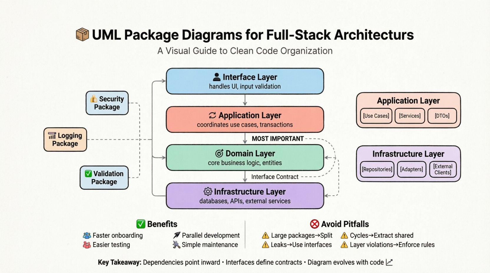
- Interface Layer: Handles all user interactions, input validation, and presentation logic.
- Application Layer: Coordinates use cases, orchestrates flows, and manages transactions.
- Domain Layer: Contains the core business logic, entities, and rules. This is the most critical part of the system.
- Infrastructure Layer: Handles external concerns like databases, file systems, and email services.
By defining these four packages, we establish a contract. Any developer working on the Domain Layer knows they should not import classes from the Infrastructure Layer. This prevents the core business rules from being tied to a specific database engine.
Step 2: Establishing Dependency Rules 🔄
Once the packages exist, the arrows must be drawn. The direction of the dependency arrow is crucial. It points from the client to the server. In a clean architecture, dependencies must point inward.
The following table illustrates the correct flow of dependencies for this project:
| Source Package | Target Package | Direction | Reasoning |
|---|---|---|---|
| Interface Layer | Application Layer | Dependency | The UI needs to trigger business processes. |
| Application Layer | Domain Layer | Dependency | Processes require business rules to execute. |
| Domain Layer | Infrastructure Layer | Dependency (via Interface) | Domain logic defines the contract, infrastructure implements it. |
| Infrastructure Layer | Domain Layer | No Dependency | Infrastructure must not know about domain entities directly. |
Notice the last row. If the Infrastructure Layer depends on the Domain Layer, it creates a “leak” of knowledge. The database code should not need to understand the specific business rules of the entity, only the data schema. This is managed through interfaces.
Step 3: Decomposing Internal Packages 🧩
As the project grows, the high-level packages will become too large to manage. The UML package diagram allows for recursive decomposition. We can open the Application Layer and see what resides inside.
Inside the Application Layer, we might find:
- Use Cases: Specific user stories mapped to code structures.
- Services: Orchestration logic that calls multiple domain objects.
- DTOs (Data Transfer Objects): Objects used to move data between layers without leaking internal state.
Similarly, the Infrastructure Layer might be split into:
- Repositories: Abstractions for data access.
- Adapters: Specific implementations for different database technologies.
- External Clients: Code that interacts with third-party APIs.
By mapping these sub-packages, we ensure that the internal structure of the application remains organized. If a new feature is added, the architect can determine exactly which sub-package it belongs to based on the diagram.
Step 4: Managing Cross-Cutting Concerns ⚙️
Every full-stack project has concerns that span across multiple layers. These include logging, authentication, caching, and error handling. If these are scattered randomly, the code becomes messy.
In the UML package diagram, these are modeled as Aspect Packages. They do not sit in the dependency chain of the business logic but attach to it via specific mechanisms.
Key cross-cutting packages include:
- Security Package: Handles token validation and permission checks.
- Logging Package: Standardizes how events are recorded across all layers.
- Validation Package: Centralizes input rules to prevent data corruption.
The diagram shows these packages as separate nodes with dashed lines or specific dependency markers indicating they are applied across the main flow. This visualization helps the team realize that if the logging mechanism changes, it might impact the Application Layer, the Domain Layer, and the Interface Layer simultaneously.
Step 5: Iteration and Refinement 📝
A package diagram is not a one-time task. It is a living document that evolves with the codebase. As the project matures, new packages will be created, and old ones will be merged.
The process of iteration involves:
- Reviewing Cycles: Every sprint, the team should review if the physical code structure matches the logical diagram.
- Identifying Cycles: If Package A depends on Package B, and Package B depends on Package A, a circular dependency exists. The diagram makes this obvious immediately.
- Refactoring: If a package becomes too large (a “God Package”), the diagram helps plan the split into smaller, cohesive units.
Without this visual guide, developers often refactor based on intuition, leading to inconsistent structures across different modules of the system.
🚫 Common Pitfalls in Package Organization
Even with a diagram, teams often fall into traps that undermine the architecture. The following table highlights common issues and their solutions.
| Pitfall | Description | Solution |
|---|---|---|
| Large Package Smell | A single package contains unrelated responsibilities. | Split the package into smaller, focused sub-packages based on functionality. |
| Dependency Cycles | Two packages depend on each other directly. | Extract the shared logic into a third package that both can depend on. |
| Implementation Leakage | Internal implementation details are exposed in the public interface. | Define strict interfaces for each package and hide internal classes. |
| Layer Violation | Lower layers depend on upper layers (e.g., Infrastructure depends on UI). | Enforce strict dependency rules and use code analysis tools to prevent violations. |
📈 Impact on Team Velocity
There is often a misconception that spending time on UML diagrams slows down development. However, the opposite is true in the long run. When the package structure is clear:
- New Hires: Can understand the system architecture within days rather than weeks. They can see where to place new code.
- Parallel Development: Teams can work on different layers simultaneously without fear of breaking changes, provided they adhere to the defined interfaces.
- Testing: Unit tests become easier to write because dependencies are explicit. Mocking becomes straightforward when interfaces are well-defined.
- Maintenance: Fixing a bug in the Domain Layer does not require navigating through UI code.
Over time, the organization provided by the package diagram reduces the “cognitive load” on developers. They spend less time searching for where a function lives and more time solving business problems.
🛠️ Integrating with Physical Structure
While the UML package diagram is logical, it must eventually map to the physical file system. The mapping strategy depends on the technology stack used, but the principle remains the same.
For a full-stack project, the directory structure should mirror the package diagram.
- Top-Level Folders: Should correspond to the high-level packages (e.g., /interface, /application, /domain).
- Sub-Folders: Should correspond to the internal packages (e.g., /domain/entities, /domain/services).
- Shared Code: If multiple layers need a utility, it should reside in a shared package that is referenced by all, rather than copied into each directory.
This alignment ensures that the file system does not contradict the architectural diagram. If a developer creates a folder that does not exist in the diagram, it signals a potential architectural debt that needs to be addressed.
🔍 Analyzing Cohesion and Coupling
The ultimate metric for a good package diagram is the balance between cohesion and coupling.
- High Cohesion: Elements within a package are closely related. They serve a single purpose. For example, all classes in the “Payment Processing” package deal only with payment logic.
- Low Coupling: Packages depend on each other as little as possible. Changes in one package do not ripple through others.
The UML diagram helps visualize this. If you see a package with 50 dependency arrows pointing outwards, it has low cohesion. It is trying to do too much. If you see a package with arrows pointing in from everywhere, it is a bottleneck. The diagram allows the architect to identify these structural weaknesses before they cause system failures.
🔄 Handling Evolution and Scaling
As the application scales, the package structure may need to shift. Perhaps the database layer needs to become a microservice. The UML package diagram facilitates this transition.
The process involves:
- Identifying Boundaries: Which packages can be separated without breaking internal dependencies?
- Defining Contracts: What interfaces must be exposed for the new service to work?
- Updating the Diagram: The diagram is updated to show the new distribution of packages across the network.
This proactive planning prevents the “big ball of mud” scenario where the system becomes too complex to split. The diagram acts as a map for migration strategies.
✅ Key Takeaways for Implementation
To successfully implement this approach, consider the following actionable points:
- Start Early: Create the package diagram during the design phase, not after coding begins.
- Keep it Simple: Do not model every class. Focus on the major groupings and their relationships.
- Enforce Rules: Use build tools or linters to prevent dependencies that violate the diagram.
- Review Regularly: Treat the diagram as part of the code review process. If the code changes, the diagram should be updated.
- Communicate: Use the diagram to explain architecture to stakeholders who may not read code.
By adhering to these principles, the project maintains a clear structure throughout its lifecycle. The organization provided by the UML package diagram is not just about drawing lines; it is about establishing a discipline that keeps the software maintainable and scalable.
Final Thoughts on Architectural Discipline
Building a full-stack system is a significant undertaking. The complexity involved requires more than just coding skills; it requires architectural foresight. The UML package diagram provides the necessary framework to organize this complexity. It forces the team to think about boundaries, dependencies, and responsibilities before implementation.
While the initial effort to create and maintain the diagram may seem high, the return on investment is visible in the stability of the codebase. Teams that invest in this modeling find that refactoring is faster, bugs are isolated more easily, and onboarding new members is less chaotic. In an industry where technology changes rapidly, the logical structure provided by these diagrams remains relevant regardless of the specific tools used.
Adopting this method ensures that the software evolves gracefully. It transforms the development process from a reactive struggle against complexity into a proactive management of structure. This is the foundation of sustainable engineering.