


Designing a database structure requires a precise language. The Entity Relationship Diagram (ERD) serves as that blueprint, translating complex data requirements into a visual format. However, not all diagrams look the same. Different industries and teams prefer different visual standards. Choosing the correct notation style impacts clarity, communication, and implementation accuracy.
This guide examines the primary ERD notation styles. We analyze their origins, symbols, and specific use cases. By understanding the nuances between Chen, Crow’s Foot, UML, and IDEF1X, you can select a standard that aligns with your project goals.
🧱 Understanding the Building Blocks
Before diving into specific styles, it is essential to understand the fundamental components common to most notation systems. Regardless of the visual style, these concepts remain consistent:
- Entities: Represented by shapes (usually rectangles). These are the objects or concepts about which data is stored, such as Customers, Orders, or Products.
- Attributes: Represented by ovals or listed within the entity box. These are the specific properties of an entity, like a Customer ID, Name, or Email Address.
- Relationships: Represented by lines or diamonds. These describe how entities interact, such as a Customer placing an Order.
- Cardinality: Defines the numerical relationship between entities (one-to-one, one-to-many, many-to-many).
- Participation: Indicates if a relationship is mandatory or optional for an entity.
While the concepts are universal, the visual representation of these blocks varies significantly across notations. This variation often dictates which audience finds the diagram easiest to interpret.
🕰️ Chen Notation: The Historical Standard
Named after Peter Chen, who introduced the concept in 1976, this is the original ERD notation. It was designed for conceptual modeling, focusing on high-level business rules rather than physical database implementation.
Key Characteristics
- Entities: Drawn as rectangles containing the entity name.
- Relationships: Drawn as diamonds connecting entities. The relationship name sits inside the diamond.
- Attributes: Drawn as ovals connected to their respective entities.
- Cardinality: Labeled directly on the lines connecting the relationship diamond to the entities.
Pros and Cons
- Pros:
- Highly readable for non-technical stakeholders.
- Excellent for conceptual and logical modeling phases.
- Clearly separates the relationship logic from the entities.
- Cons:
- Can become cluttered with complex many-to-many relationships.
- Not standard for physical database schema generation.
- Requires specific translation to be implemented in SQL.
Chen notation is particularly useful during the initial discovery phase. When business analysts discuss data requirements with subject matter experts, the diamond shapes make the verbs (relationships) stand out distinctly from the nouns (entities).
🦶 Crow’s Foot Notation: The Industry Standard
Developed by Gordon Everest based on the work of William Kent and later popularized by Gordon Everest and others, Crow’s Foot is the most widely used notation for relational database design. It is often simply referred to as the “Chen-to-Crow’s Foot” transition in modern documentation.
Key Characteristics
- Entities: Rectangles (often with primary keys listed inside).
- Relationships: Straight lines connecting entities. No diamonds are used.
- Cardinality Symbols: The ends of the lines use specific symbols:
- Single Line: Represents one.
- Crow’s Foot (Three prongs): Represents many.
- Vertical Bar (|): Represents mandatory participation.
- Circle (O): Represents optional participation.
Pros and Cons
- Pros:
- Directly maps to relational database structures.
- Compact and efficient for complex schemas.
- Widely recognized by database administrators and developers.
- Supports detailed physical modeling.
- Cons:
- Can be dense and harder for non-technical users to parse quickly.
- Requires learning specific symbol conventions (e.g., the crow’s foot).
Crow’s Foot is the default choice for most modern software projects involving SQL databases. Because it explicitly shows foreign key constraints through the lines, it reduces ambiguity during the physical implementation phase.
🏗️ UML Class Diagrams: The Object-Oriented Approach
The Unified Modeling Language (UML) is primarily used in software engineering, specifically for object-oriented programming. While often distinct from traditional ERDs, UML Class Diagrams are frequently used to model data structures in systems that bridge the gap between code and data.
Key Characteristics
- Entities: Represented as Classes. These are rectangles divided into three sections: Class Name, Attributes, and Operations (methods).
- Relationships: Lines connecting classes with specific arrows.
- Cardinality: Written as numbers (e.g., 0..1, 1..*, 0..*) near the ends of the lines.
- Visibility: Symbols like + (public), – (private), or # (protected) are often included.
Pros and Cons
- Pros:
- Seamlessly integrates data models with code structures.
- Best for systems built on object-oriented frameworks.
- Standardized across the software development lifecycle.
- Cons:
- Overkill for simple database design.
- Focuses heavily on behavior (methods), which may distract from pure data modeling.
Use UML when your team is predominantly developers rather than data modelers. It ensures that the database schema aligns perfectly with the classes defined in the application code.
📜 IDEF1X: The Structured Standard
Integrated Definition for Information Modeling (IDEF1X) is a standard developed for the U.S. Department of Defense. It is highly rigorous and designed for large-scale, complex system integration.
Key Characteristics
- Entities: Rectangles with a specific layout.
- Relationships: Lines with strict rules on how they connect.
- Identification: Distinguishes clearly between Identifying and Non-Identifying relationships.
- Constraints: Enforces strict rules on subtyping and categorization.
Pros and Cons
- Pros:
- Extremely precise and unambiguous.
- Handles complex inheritance and categorization well.
- Industry standard for government and large enterprise contracts.
- Cons:
- Steep learning curve for new users.
- Often considered too rigid for agile development environments.
📊 Comparison of Notation Styles
To assist in decision-making, the following table summarizes the key differences between the major styles.
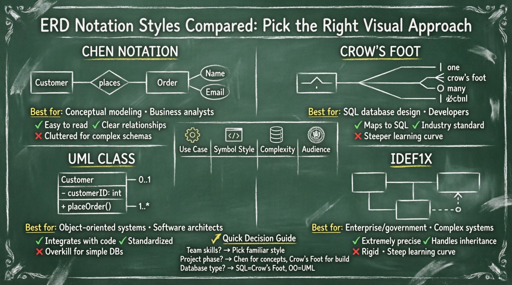
| Feature | Chen Notation | Crow’s Foot | UML Class Diagram | IDEF1X |
|---|---|---|---|---|
| Primary Use | Conceptual Modeling | Physical Database Design | Software Engineering | System Integration |
| Relationship Symbol | Diamond | Line + End Symbols | Line + Arrow | Line + Specific End |
| Cardinality Display | Labels on lines | End Symbols (Crow’s Foot) | Numbers (0..1) | Strict End Symbols |
| Complexity | Low to Medium | Medium | Medium to High | High |
| Best Audience | Business Analysts | DBAs, Developers | Software Architects | Enterprise Architects |
🤔 Factors Influencing Your Choice
Selecting a notation is not merely an aesthetic decision. It affects how information flows through the project lifecycle. Consider the following factors:
- Team Composition: If your team consists of business analysts, Chen notation might reduce friction. If the team is composed of backend engineers, Crow’s Foot is likely the preferred standard.
- Database Type: Relational databases (SQL) align naturally with Crow’s Foot. Object-oriented databases or NoSQL systems might benefit more from UML representations.
- Project Phase: Early conceptual phases often use Chen to avoid getting bogged down in implementation details. Physical design phases require Crow’s Foot or IDEF1X to define constraints accurately.
- Documentation Standards: Some organizations have strict compliance requirements that mandate specific standards like IDEF1X.
- Tooling: While you should not rely on specific software, the capabilities of your modeling environment may favor one style. Some tools automatically generate SQL from Crow’s Foot but not Chen.
🛠️ Implementation Considerations
Once a notation is selected, consistency is paramount. Ambiguity in diagrams leads to errors in the schema. Ensure the following practices are followed:
- Standardize Naming Conventions: Use singular nouns for entities (e.g., “Customer” not “Customers”).
- Define Primary Keys Explicitly: Mark the primary key attribute clearly in every entity.
- Document Participation: Clearly mark mandatory vs. optional relationships. A circle on the line indicates optional participation, while a bar indicates mandatory.
- Review Cardinality: Double-check that the crow’s foot direction matches the business rule. Does one customer place many orders, or does one order belong to many customers?
- Version Control: Treat diagrams as code. Maintain history to track how relationships evolved over time.
⚠️ Common Pitfalls to Avoid
Even with the correct notation, errors occur. Be vigilant against these common mistakes:
- Chasing Relationships: Avoid creating circular dependencies where A relates to B, B relates to C, and C relates back to A without a clear path. This often indicates a missing entity.
- Mixing Notations: Do not mix Chen diamonds with Crow’s Foot lines in the same diagram. It creates confusion for the reader.
- Ignoring Nullability: Ensure that the diagram reflects whether a foreign key can be null. This is critical for data integrity.
- Over-Modeling: Do not model every single attribute in the initial conceptual phase. Focus on relationships first. Details can be added later.
- Assuming Implicit Knowledge: Do not assume stakeholders understand what a specific line symbol means. Add a legend or keys to the diagram.
🚀 Moving Forward
The choice of ERD notation ultimately depends on the context of your project. There is no single “best” style. Chen notation offers clarity for business logic. Crow’s Foot provides precision for database engineering. UML bridges the gap to application code. IDEF1X ensures rigorous compliance.
By understanding the strengths and limitations of each style, you can build diagrams that communicate effectively. This leads to fewer misunderstandings, cleaner schemas, and smoother project delivery. Evaluate your team’s needs and the specific goals of your data architecture before committing to a visual standard.
Remember that the diagram is a tool for communication, not just a technical artifact. A well-chosen notation ensures that the vision of the data structure is understood by everyone involved, from the stakeholder defining the requirements to the developer writing the SQL queries.
📝 Summary Checklist
- ✅ Assess the technical skills of your team.
- ✅ Determine the phase of the project (Conceptual vs. Physical).
- ✅ Select a notation that aligns with your database technology.
- ✅ Enforce consistency in symbols and labels.
- ✅ Include a legend for complex symbols.
- ✅ Review the diagram with both technical and non-technical members.
Adopting the right visual approach streamlines the entire data modeling process. It reduces the time spent clarifying ambiguities and ensures that the final database structure accurately reflects the business requirements.