


In the landscape of data architecture, few concepts create more confusion than the many-to-many relationship. When designing an Entity-Relationship Diagram (ERD), encountering a situation where one entity connects to multiple instances of another, and vice versa, requires a specific structural approach. Relational database management systems do not natively support direct many-to-many associations. They require an intermediate structure to maintain data integrity and ensure efficient querying. This guide explores the authoritative methods for resolving these associations, ensuring your data model remains robust, scalable, and normalized.
Whether you are designing a system for academic records, inventory management, or user permissions, the principles of resolving these cardinalities remain constant. Understanding the underlying mechanics prevents future anomalies and simplifies maintenance. We will move beyond surface-level definitions to examine the structural requirements, normalization rules, and implementation strategies that define professional data modeling.
🔍 Understanding Cardinality in ERDs
Cardinality defines the numerical relationship between entities in a database. It specifies the number of instances of one entity that can or must be associated with each instance of another entity. In ERD notation, this is often represented by lines connecting entities, with crow’s feet indicating the “many” side and straight lines or single ticks indicating the “one” side.
There are three primary cardinalities:
- One-to-One (1:1): A single record in Entity A relates to a single record in Entity B. Example: A person and their passport.
- One-to-Many (1:M): A single record in Entity A relates to multiple records in Entity B. Example: A customer placing multiple orders.
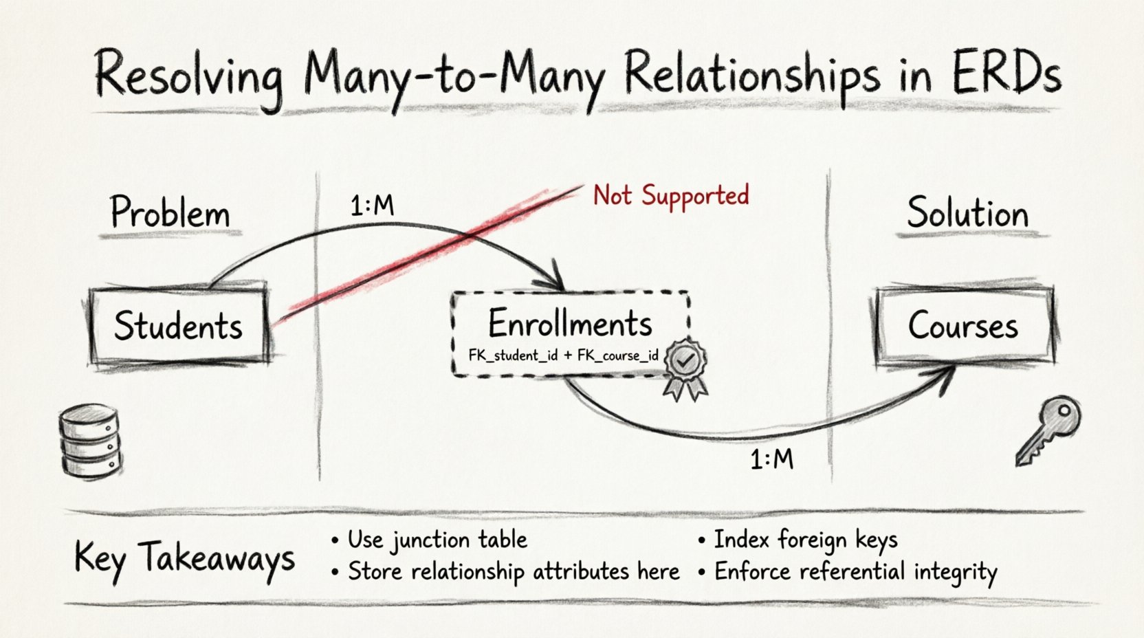
- Many-to-Many (M:N): Multiple records in Entity A relate to multiple records in Entity B. Example: Students enrolling in multiple courses, and courses containing multiple students.
While 1:1 and 1:M relationships are straightforward to implement in a physical database schema, the M:N relationship presents a unique challenge. Relational theory dictates that a table cell should contain only atomic values. A direct link between two tables where a single row in Table A could theoretically reference multiple rows in Table B violates this principle in the physical layer.
🚫 Why Direct M:M Relationships Fail in Relational Models
The relational model, established by E.F. Codd, relies on the concept of relations (tables) where each column represents a specific attribute and each row represents a unique instance. There are two primary reasons why a direct many-to-many link is impossible in a standard relational database:
- Lack of Native Support: Database engines do not allow a foreign key column to hold multiple values. A foreign key must point to a single primary key in another table. It cannot point to a list of keys.
- Insertion and Deletion Anomalies: If you attempt to store multiple IDs in a single cell (e.g., “Student_ID: 101, 102, 103”), you create a violation of First Normal Form (1NF). This makes querying, updating, and deleting specific relationships computationally expensive and error-prone.
Consequently, to store this data efficiently, the relationship itself must be treated as an entity. This transformation is the core technique for resolving the complexity.
🧱 Technique 1: The Associative Entity (Junction Table)
The standard solution for resolving a many-to-many relationship is the creation of an associative entity, commonly known as a junction table or bridge table. This table sits physically between the two primary entities and breaks the direct connection into two one-to-many relationships.
When you introduce a junction table, the original M:N relationship is decomposed into:
- A one-to-many relationship between Entity A and the Junction Table.
- A one-to-many relationship between Entity B and the Junction Table.
Structure of a Junction Table:
- Foreign Keys: It must contain at least two foreign key columns. One references the primary key of Entity A, and the other references the primary key of Entity B.
- Composite Primary Key: Often, the combination of these two foreign keys serves as the primary key for the junction table. This ensures that a specific pair of entities cannot be linked more than once unless the relationship is inherently multi-valued.
- Surrogate Keys: In some cases, a unique auto-incrementing ID is added to the junction table. This is useful if the relationship can have multiple instances with different attributes (e.g., a student can be enrolled in a course multiple times with different grades over different years).
Example Scenario:
Consider a library system. A Book can be borrowed by many Patrons. A Patron can borrow many Books.
- Without resolution: You cannot link one book row to multiple patron rows directly.
- With resolution: Create a Borrowing_Log table.
- The Borrowing_Log contains
Book_IDandPatron_ID.
This structure allows the database to track exactly which patron has which book at any given time without duplicating book or patron data.
📝 Technique 2: Handling Attributes on Relationships
A critical distinction in ERD modeling is whether the relationship between entities carries its own data. In a simple link, the connection exists or it does not. However, in many real-world scenarios, the relationship itself has properties.
For example, in a Project and Employee scenario, an employee can work on multiple projects, and a project has multiple employees. But the relationship might include:
- Role: Is the employee a developer, designer, or manager on this specific project?
- Hours_Allocated: How many hours per week are assigned to this project?
- Start_Date: When did this assignment begin?
If you treat the relationship merely as a binary flag, you lose this essential data. The junction table becomes the perfect place to store these attributes.
Implementation Rules:
- Do not store relationship attributes in the parent entities. They do not belong to the Project alone, nor the Employee alone.
- Place all relationship-specific data in the junction table.
- Ensure the junction table has a unique identifier (composite or surrogate) to allow for updates to these attributes without affecting the parent entities.
This approach ensures data normalization. If you were to add a Role column to the Employee table, it would create redundancy if the employee has multiple roles across different projects. The junction table isolates this variation.
⚖️ Technique 3: Normalization and Data Integrity
Resolving M:N relationships is not just about linking tables; it is about adhering to normalization principles to prevent data anomalies. The Third Normal Form (3NF) is the standard target for most transactional systems.
Third Normal Form (3NF) Requirements:
- The table must be in Second Normal Form (2NF).
- All non-key attributes must depend only on the primary key.
By creating a junction table, you ensure that the relationship data depends on the composite key of the junction table, not on the individual entity keys. This eliminates transitive dependencies.
Referential Integrity:
Foreign key constraints are essential in the junction table. They enforce the following rules:
- A
Book_IDin the borrowing log must exist in the Books table. - A
Patron_IDin the borrowing log must exist in the Patrons table.
This prevents orphaned records. You cannot log a borrowing event for a book that does not exist in the catalog. Database engines enforce this through CASCADE or RESTRICT actions on delete.
📊 Comparison of Relationship Types
Visualizing the differences between relationship types helps in selecting the correct modeling strategy. The table below summarizes the structural requirements and implementation complexity.
| Relationship Type | Physical Implementation | Primary Key Location | Complexity |
|---|---|---|---|
| One-to-One (1:1) | Foreign key in one table | Either table | Low |
| One-to-Many (1:M) | Foreign key in the “many” table | Primary table | Medium |
| Many-to-Many (M:N) | Separate junction table | Junction table (composite) | High |
As shown, the M:N relationship requires the most structural overhead. However, this overhead is necessary for data integrity. The cost of an extra join during a query is often outweighed by the cost of data inconsistency in a poorly modeled schema.
🚀 Performance Considerations
Introducing a junction table adds a layer of indirection to your queries. When retrieving data, you must join three tables instead of two. In high-volume systems, this can impact performance if not managed correctly.
- Indexing: Every foreign key in the junction table should be indexed. This allows the database engine to quickly locate rows for a specific entity without scanning the entire junction table.
- Composite Indexes: In some cases, creating an index on the combination of both foreign keys is more efficient than separate indexes. This supports queries that filter by both entities simultaneously.
- Read vs. Write: Junction tables are typically write-heavy if relationships are dynamic. They are read-heavy when generating reports. Ensure your indexing strategy supports the dominant operation pattern of your application.
⚠️ Common Pitfalls and Solutions
Even experienced modelers make mistakes when resolving cardinalities. Awareness of common errors can save significant refactoring time later.
1. The “One-Column” Mistake
Attempting to store multiple IDs in a single column using comma-separated values (e.g., “1, 2, 3”). This violates database principles and makes querying impossible without string parsing functions. Always use a separate row for each relationship instance.
2. Redundant Attributes
Copying attributes from the parent entities into the junction table without necessity. If an attribute belongs to the entity (e.g., a Student’s Name), it belongs in the Student table, not the Enrollment table. Only put data that describes the link itself.
3. Ignoring Nullability
Defining foreign keys as nullable when they should be mandatory. If a relationship is mandatory (e.g., an Order must have a Customer), the foreign key should not allow NULL values. This enforces business rules at the database level.
4. Circular References
Creating a junction table that references itself unnecessarily. Ensure the junction table only links the two distinct entities involved in the relationship. Avoid creating loops that do not serve a functional purpose.
🎨 Visual Representation Best Practices
When documenting your ERD, clarity is paramount. The visual representation should immediately convey the resolved structure to anyone reading the diagram.
- Label the Junction Table: Name the table descriptively. Instead of “Table3”, use “Student_Course_Enrollment”.
- Indicate Cardinality: Clearly mark the lines connecting the junction table to the parent entities. Use crow’s feet on the junction table side to show the “many” relationship from the parent’s perspective.
- Show Attributes: If the junction table has attributes (like “Grade” or “Date”), list them explicitly in the diagram. This highlights that the relationship is more than just a link.
- Use Different Line Styles: Some modeling tools allow dashed lines for optional relationships and solid lines for mandatory ones. Consistency here aids understanding.
🔄 Recursive Relationships and M:N
Occasionally, a many-to-many relationship exists within a single entity. For example, an Employee can manage multiple other Employees, and those employees can manage others. This is a recursive M:N relationship.
The resolution remains the same as a standard M:N relationship. You still create a junction table, but both foreign keys in that table reference the primary key of the same entity.
- Entity: Employee
- Junction Table: Employee_Management
- FK1: Manager_ID (References Employee)
- FK2: Subordinate_ID (References Employee)
This structure allows for complex organizational hierarchies without violating normalization rules. It enables queries to traverse multiple levels of management depth.
🛡️ Data Constraints and Business Rules
Technical constraints are not enough; business rules must be enforced. A junction table provides a natural place to apply these rules.
- Unique Constraints: Ensure that a specific relationship cannot be created twice unless intended. For example, a student should not be enrolled in the same course section twice in the same semester. A unique constraint on the combination of Student_ID and Course_ID enforces this.
- Check Constraints: Validate numeric data. For instance, the “Hours_Allocated” in a project junction table must be greater than zero and less than 40.
- Triggers: In complex systems, triggers may be required to update summary tables. If the junction table changes, a summary table in the parent entity (e.g., “Total_Projects_Per_Employee”) might need updating automatically.
📈 Evolution of the Model
Models evolve as requirements change. A relationship that starts as many-to-many might simplify to one-to-many if a business rule changes. For instance, if a policy changes such that a student can only enroll in one course at a time, the junction table can be merged back into the student table.
However, starting with the junction table is generally safer. It accommodates the maximum flexibility. If the requirement changes later to allow multiple enrollments, the schema is already prepared. If you start with a merged table, you must refactor later.
📝 Summary of Key Takeaways
Resolving many-to-many relationships is a fundamental skill in database design. It requires the creation of an intermediate structure to maintain data integrity and support efficient queries. The junction table is the standard solution, breaking complex associations into manageable one-to-many links.
- Always resolve M:N: Never attempt to store multiple foreign keys in a single column.
- Use composite keys: The combination of foreign keys often serves as the unique identifier for the relationship.
- Store relationship data: Place attributes specific to the link in the junction table.
- Index foreign keys: Performance depends on fast lookups of the junction table rows.
- Enforce constraints: Use unique constraints and foreign key references to prevent invalid data.
By adhering to these techniques, you ensure that your database schema is resilient to change and capable of handling complex data interactions. The effort invested in proper modeling during the design phase pays dividends in maintainability and performance throughout the lifecycle of the system.