


Understanding how data connects is fundamental to building robust systems. When you encounter a database schema without documentation, an Entity-Relationship Diagram (ERD) becomes your primary source of truth. This guide provides a structured approach to interpreting these diagrams, ensuring you can navigate complex data models with clarity and precision. We will cover the core symbols, relationship types, and analytical steps required to decode any schema effectively.
Why Understanding ERDs Matters 🧠
Database schemas are rarely self-explanatory. A well-documented ERD serves as a blueprint, showing how information is stored, linked, and validated. Whether you are a developer integrating a new service, a business analyst gathering requirements, or a database administrator performing maintenance, the ability to read these diagrams is essential.
- System Integration: Knowing foreign key relationships prevents data integrity errors during migration.
- Performance Tuning: Understanding join paths helps optimize query execution.
- Communication: A shared visual language bridges the gap between technical teams and stakeholders.
- Legacy Maintenance: Decoding older systems relies heavily on reverse-engineering existing diagrams.
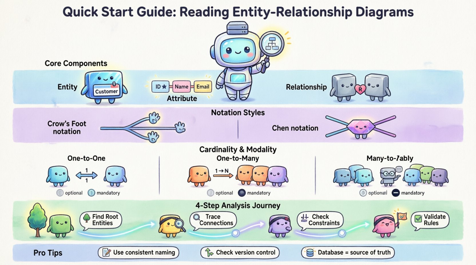
Core Components of a Database Schema 🏗️
Before analyzing complex structures, you must identify the building blocks. Every ERD is constructed from three primary elements. Recognizing these immediately allows you to break down the diagram into manageable sections.
1. Entities 🏷️
An entity represents a distinct object or concept within the system. In a relational context, this usually maps to a table. Entities are typically drawn as rectangles.
- Examples: Customer, Product, Order, Employee.
- Visual Cue: A box containing the entity name.
- Key Identifier: Each entity should have a primary key to ensure uniqueness.
2. Attributes 📝
Attributes are the specific data points that describe an entity. They define the columns within a table. While some notations place attributes inside the entity box, others connect them with lines.
- Primary Key: Often underlined, this uniquely identifies a record.
- Foreign Key: Links to the primary key of another entity.
- Data Types: Implicitly defined by the context (e.g., dates, integers, strings).
3. Relationships 🔗
Relationships define how entities interact. They indicate constraints and dependencies between records. In diagrams, these are usually lines connecting the entities.
- Direction: Shows which entity initiates the connection.
- Constraint: Indicates if a relationship is mandatory or optional.
- Cardinality: Defines the numeric limit of connections (e.g., one to many).
Decoding Standard Notations 🔍
Different teams and tools use various styles to represent the same concepts. The two most common styles are the Crow’s Foot notation and the Chen notation. Recognizing the style helps you interpret the lines correctly.
Comparison of Notation Styles
| Feature | Crow’s Foot Notation | Chen Notation |
|---|---|---|
| Entities | Rectangles | Rectangles |
| Relationships | Lined connectors with symbols | Diamonds connecting lines |
| Cardinality | Lines with specific endings (e.g., crow’s foot) | Numbers placed on the lines |
| Complexity | Compact, popular in modern tools | Explicit, often used in academic contexts |
When reviewing a diagram, locate the legend or check the style of the lines. If you see diamond shapes, you are looking at Chen notation. If you see lines ending in three prongs, you are looking at Crow’s Foot notation. Both convey the same logic but use different visual metaphors.
Understanding Cardinality and Modality 🔄
Cardinality is the most critical aspect of an ERD. It dictates the business rules regarding data quantity. Misinterpreting this leads to flawed database designs and application logic errors.
Common Cardinality Types
- One-to-One (1:1): A record in Table A is linked to exactly one record in Table B.
- One-to-Many (1:N): A record in Table A is linked to multiple records in Table B.
- Many-to-Many (M:N): Records in Table A link to multiple records in Table B, and vice versa. This usually requires a junction table.
Modality (Optionality)
Modality determines if a relationship is mandatory or optional. This is often indicated by a vertical bar (|) or a circle (o) on the line connecting entities.
| Symbol | Meaning | Example Scenario |
|---|---|---|
| Circle (o) | Optional | A user may have a profile picture. |
| Bar (|) | Mandatory |
Step-by-Step Analysis Process 📝
Approaching a complex diagram can be overwhelming. Follow this systematic workflow to ensure you capture all necessary details without missing critical constraints.
Step 1: Identify the Root Entities 🌳
Start with the central actors. These are the primary subjects of the system. Look for entities that have the most connections.
- Identify the main business objects.
- Note their primary keys.
- Verify if they are the source of truth for the data.
Step 2: Trace the Connections 🔍
Follow the lines from one entity to another. Do not jump around. Trace a single path fully before moving to the next.
- Read the labels on the relationship lines.
- Check the cardinality markers at both ends.
- Verify if foreign keys are explicitly named.
Step 3: Check Attribute Constraints ⚖️
Look inside the entity boxes for specific data rules.
- Are there unique constraints on non-key columns?
- Are there default values indicated?
- Is there a composite key (multiple columns forming one key)?
Step 4: Validate Integrity Rules ✅
Ensure the diagram aligns with logical business requirements.
- Does a child entity depend on the parent for existence?
- Are there circular dependencies that might cause issues?
- Is the data normalization level appropriate (e.g., 3NF)?
Common Relationship Patterns 🏛️
Certain patterns appear frequently across different industries. Recognizing these shortcuts can speed up your interpretation time significantly.
1. The Hierarchical Pattern
This structure resembles a tree. One parent connects to many children, who connect to their own children. This is common in organizational charts or category trees.
- Structure: Parent → Child → Grandchild.
- Implementation: Self-referencing foreign keys in the same table.
- Warning: Deep nesting can impact query performance.
2. The Star Schema Pattern
Often used in data warehousing. A central fact table connects to multiple dimension tables.
- Structure: One central hub, many spokes.
- Usage: Aggregation and reporting scenarios.
- Benefit: Simplifies complex queries for analytics.
3. The Junction Table Pattern
Required for Many-to-Many relationships. Two entities cannot link directly without an intermediate table.
- Structure: Table A ↔ Junction ↔ Table B.
- Function: Stores foreign keys from both sides plus any specific attributes of the link.
- Example: Students and Courses (a student takes many courses; a course has many students).
Best Practices for Documentation 📚
A diagram is only as good as its accompanying documentation. When you encounter an existing ERD, check if it meets these standards.
- Consistent Naming: Use singular nouns for entities (e.g., User not Users). Use camelCase or snake_case consistently for columns.
- Clear Legend: Ensure symbols are defined if the notation is non-standard.
- Version Control: Diagrams change. Ensure the version matches the current database state.
- Metadata: Include author names and update dates on the diagram itself.
- Logical vs. Physical: Distinguish between the conceptual design (business rules) and the physical design (data types, indexes).
Troubleshooting Ambiguities 🔧
Not all diagrams are perfect. You may encounter vague symbols or missing information. Here is how to handle those gaps.
Missing Cardinality
If a line has no end markers, assume the relationship is unknown. Do not guess. Verify with the development team or check the database schema directly via system tables.
Inconsistent Foreign Keys
If the diagram shows a relationship but the database lacks the foreign key constraint, the diagram is outdated. Prioritize the actual database structure for implementation tasks.
Orphaned Entities
Entities that have no connections might be deprecated or incorrectly modeled. Investigate if they are still in use before removing them from your mental model.
Advanced Considerations 🚀
Once you are comfortable with the basics, consider these advanced factors that affect how you interpret the data model.
1. Inheritance and Supertypes
Some diagrams use triangles or special lines to indicate inheritance. This means one entity is a specialized version of another (e.g., Vehicle is a supertype of Car and Bike).
- Shared Attributes: Inherited from the parent.
- Specific Attributes: Unique to the child.
- Implementation: Often handled via a single table with type columns or multiple tables with shared keys.
2. Recursive Relationships
An entity can relate to itself. This is common in approval workflows or hierarchical data.
- Example: An Employee supervises other Employees.
- Visual: A line looping back to the same box.
3. Weak Entities
These entities cannot exist without a parent. Their primary key includes a foreign key from the parent.
- Visual: Often drawn with a double rectangle.
- Implication: Deleting the parent deletes the child automatically.
Final Thoughts on Schema Interpretation 📄
Reading an Entity-Relationship Diagram is a skill that improves with practice. It requires patience to trace every line and verify every constraint. By breaking the diagram down into entities, attributes, and relationships, you transform a complex visual into a logical understanding of the data.
Remember that diagrams are living documents. They should evolve as the system changes. When you find discrepancies between the drawing and the code, treat the database as the source of truth. Use the diagram to understand the intent, but rely on the schema for execution.
With this foundation, you are equipped to approach any database architecture. You can identify bottlenecks, understand data flow, and communicate effectively with stakeholders about how information is stored and managed. Focus on the logic behind the lines, and the technical details will follow naturally.