


Software engineering relies heavily on visual communication to bridge the gap between abstract requirements and concrete implementation. Among the various modeling techniques available, the use case diagram stands out as a fundamental tool for capturing functional requirements. It provides a high-level view of system behavior without getting bogged down in implementation details. This guide explores the mechanics, structure, and strategic application of use case diagrams within the software development lifecycle.
Understanding the Core Purpose 🎯
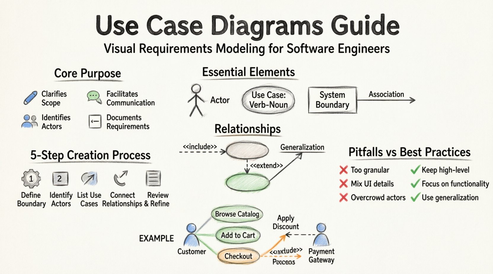
A use case diagram serves as a visual contract between the system and its users. It defines what the system does, not how it does it. This distinction is critical for maintaining clarity during the analysis phase. By focusing on functionality, stakeholders can validate requirements before development begins.
- Clarifies Scope: It delineates what is inside the system boundary and what is outside.
- Facilitates Communication: It provides a common language for developers, testers, and business analysts.
- Identifies Actors: It highlights who or what interacts with the system.
- Documents Requirements: It captures functional requirements in a standardized format.
When creating these diagrams, the goal is precision. Ambiguity in a diagram leads to ambiguity in code. Therefore, every element must have a clear definition.
Essential Elements of a Use Case Diagram 🧩
To construct a valid diagram, one must understand the standard components defined in the Unified Modeling Language (UML). Each component has a specific role and notation.
1. Actors 👤
An actor represents a role played by an external entity interacting with the system. Actors are not necessarily people; they can be other systems or hardware devices.
- Primary Actors: These initiate the use case and are the main reason the system exists.
- Secondary Actors: These support the primary actor or system in completing a use case.
- System Boundary: The rectangle enclosing the use cases separates the system from the actors.
Notation:
- Drawn as a stick figure.
- Name placed below the figure.
- Positioned outside the system boundary rectangle.
2. Use Cases ⚡
A use case represents a specific function or service the system provides. It is a complete unit of functionality that delivers value to an actor.
- Granularity: Use cases should be atomic. Avoid combining unrelated actions into one bubble.
- Naming: Use a verb-noun phrase (e.g., “Process Payment” rather than “Payment”).
- Identification: Drawn as an oval or ellipse.
- Label: Text placed inside or below the oval.
3. Associations 🔗
An association links an actor to a use case. It indicates that the actor interacts with the system to perform that specific function.
- Directionality: Typically shown as a line without an arrow, though some conventions use arrows to indicate the initiator of the flow.
- Multiplicity: Can be optional (0..1) or mandatory (1..1) depending on the interaction rules.
Relationships and Dependencies 🔄
Simple associations are not enough to describe complex system behaviors. Relationships allow you to express how use cases interact with one another.
Relationship Types Table 📊
| Relationship | Stereotype | Meaning | Visual Notation |
|---|---|---|---|
| Include | 📅 <<include>> | One use case must incorporate another. The included behavior is part of the base use case. | Dashed line with arrow pointing to included use case. |
| Extend | 📦 <<extend>> | One use case may add behavior to another under specific conditions. | Dashed line with arrow pointing to extending use case. |
| Generalization | 👇 <<generalization>> | Inheritance relationship. A specialized actor or use case inherits properties from a parent. | Solid line with a hollow triangle arrow. |
Deep Dive: Include vs. Extend
Confusion often arises between include and extend relationships. Understanding the difference is vital for accurate modeling.
- Include: Think of this as a subroutine. If you use “Check Out,” you must “Calculate Total.” The logic is mandatory. The arrow points from the base use case (Check Out) to the included use case (Calculate Total).
- Extend: Think of this as an optional addition. “Check Out” can be extended by “Apply Coupon” if the user has a coupon. The arrow points from the extension (Apply Coupon) to the base use case (Check Out).
Using the correct relationship prevents logical errors in the design phase. It clarifies when a step is required versus when it is situational.
Step-by-Step Process for Creation 📝
Creating a use case diagram is not a solo activity. It requires collaboration and a structured approach. Follow this workflow to ensure accuracy.
Step 1: Identify the System Boundary
Define what is included in the system and what is external. Draw a large rectangle. Everything inside is the system. Everything outside is the environment.
Step 2: Identify Actors
Brainstorm all roles that interact with the system. Ask:
- Who starts the process?
- Who receives the result?
- Who manages the data?
- Are there external systems involved?
Group similar roles if necessary. For example, “Manager” and “Supervisor” might be generalized into “Admin” if they share the same permissions.
Step 3: Identify Use Cases
For each actor, list the actions they can perform. Use the verb-noun convention. Review the list to ensure no duplicates exist.
- Review for overlapping functionality.
- Ensure every use case provides value to an actor.
- Verify that the use case fits within the system boundary.
Step 4: Define Relationships
Connect actors to use cases with association lines. Then, analyze the use cases for dependencies.
- Does one use case always require another? (Include)
- Does one use case add optional behavior to another? (Extend)
- Are there shared behaviors that can be generalized? (Generalization)
Step 5: Review and Refine
A diagram is never perfect on the first draft. Review it with stakeholders.
- Check for orphaned actors (actors with no connections).
- Check for isolated use cases (use cases with no actors).
- Ensure the diagram is readable and not cluttered.
Common Pitfalls to Avoid ⚠️
Even experienced engineers make mistakes when modeling systems. Being aware of common errors helps maintain diagram integrity.
| Pitfall | Why It Is Incorrect | Correct Approach |
|---|---|---|
| Designing the Interface | Use case diagrams focus on functionality, not UI screens. | Keep the focus on what the system does, not how the user clicks. |
| Too Many Actors | Overcrowding the diagram makes it unreadable. | Group similar actors or use generalization to reduce visual noise. |
| Using Flowcharts | Use cases are not step-by-step sequences. | Reserve flowcharts for detailed process logic. Use cases for high-level scope. |
| Mixing Data Flows | Data flow diagrams show data movement; use case diagrams show interactions. | Separate data modeling from functional modeling. |
Best Practices for Clarity and Maintenance 🛡️
Maintaining diagrams over time is often harder than creating them. Software evolves, and diagrams must evolve with it.
1. Keep It High-Level
Do not include every single button click. A use case like “Click Button” is too granular. Instead, group actions into meaningful goals like “Submit Form”.
2. Use Consistent Naming Conventions
Establish a standard for naming actors and use cases. Consistency reduces cognitive load for anyone reading the diagram.
- Use present tense verbs for use cases (e.g., “Retrieve Report”).
- Use noun phrases for actors (e.g., “Customer”).
3. Version Control the Diagrams
Just like code, diagrams should be versioned. Track changes in functionality to ensure the diagram matches the current system state.
4. Integrate with Documentation
A diagram alone is insufficient. It should be accompanied by use case descriptions or scenarios that detail the preconditions, postconditions, and main flow of events.
Integration with the Software Development Lifecycle 🔄
Use case diagrams are not static artifacts. They are living documents that participate in the development lifecycle.
- Requirements Phase: They help capture stakeholder needs and validate scope.
- Design Phase: They guide the architecture by identifying key functional boundaries.
- Testing Phase: Test cases are often derived directly from use case scenarios.
- Maintenance Phase: They serve as a reference for understanding existing functionality during refactoring.
Example Scenario: E-Commerce System
Consider a simplified e-commerce platform. The diagram would contain the following elements:
- Actor: Customer
- Actor: Payment Gateway
- Use Case: Browse Catalog
- Use Case: Add to Cart
- Use Case: Checkout
- Use Case: Process Payment (Included in Checkout)
- Use Case: Apply Discount (Extends Checkout)
In this scenario, the system boundary encloses the catalog, cart, and payment logic. The Customer interacts with the front end. The Payment Gateway is an external system interacting via the Process Payment use case.
Advanced Considerations 🧠
As systems grow in complexity, basic diagrams may need to be supplemented with additional modeling techniques.
1. Actor Inheritance
If you have a “Manager” actor that performs all tasks of a “User” actor plus some additional ones, use generalization. The Manager is a specialized User. This reduces redundancy in the diagram.
2. Use Case Inheritance
Similarly, a “Premium Checkout” use case might extend the standard “Checkout” use case. This indicates shared logic with specific additions.
3. Multiple Diagrams
Do not try to fit an entire enterprise system into one diagram. It will become unreadable. Split the system into subsystems and create separate use case diagrams for each. Link them using common actors or use case packages.
Conclusion 🏁
Mastering the art of use case diagrams requires practice and discipline. It is a skill that improves over time as you gain experience with different system architectures. By adhering to standard notations, avoiding common pitfalls, and maintaining clear relationships between actors and functions, you can create diagrams that serve as effective communication tools.
Remember that the value of a diagram lies in its ability to convey information accurately. A diagram that is too complex defeats its purpose. A diagram that is too simple fails to capture necessary details. Strive for the balance that best serves your specific project needs. Regularly review these models to ensure they remain accurate reflections of your software. This ongoing commitment to documentation quality leads to more robust systems and smoother development processes.