


Understanding system behavior is a fundamental requirement for successful software architecture and business analysis. Among the various modeling techniques available, the Use Case Diagram stands out as a critical tool for visualizing interactions between users and systems. This visual representation helps stakeholders understand the functional requirements of a system without getting bogged down in technical implementation details. Whether you are a business analyst, a software developer, or a project manager, grasping the mechanics of a Use Case Diagram is essential for clear communication and effective system design.
This comprehensive guide delves into the core concepts, standard symbols, and relationship types that define the UML Use Case Diagram. We will explore how to construct these diagrams effectively, avoid common pitfalls, and ensure your models serve their intended purpose: bridging the gap between human intent and system capability.
📋 What is a Use Case Diagram?
A Use Case Diagram is a type of Unified Modeling Language (UML) diagram that illustrates the interactions between external entities and a system. It focuses on what the system does, rather than how it does it. This distinction is vital for capturing requirements early in the development lifecycle.
At its core, a Use Case Diagram provides a high-level view of the system’s functionality. It maps out the goals that different users or external systems aim to achieve. By visualizing these goals, teams can identify scope, detect missing requirements, and validate the system against user needs before writing a single line of code.
👥 Key Components of a Use Case Diagram
To understand the diagram fully, one must recognize its primary building blocks. These elements form the grammar of the visual language used in system modeling.
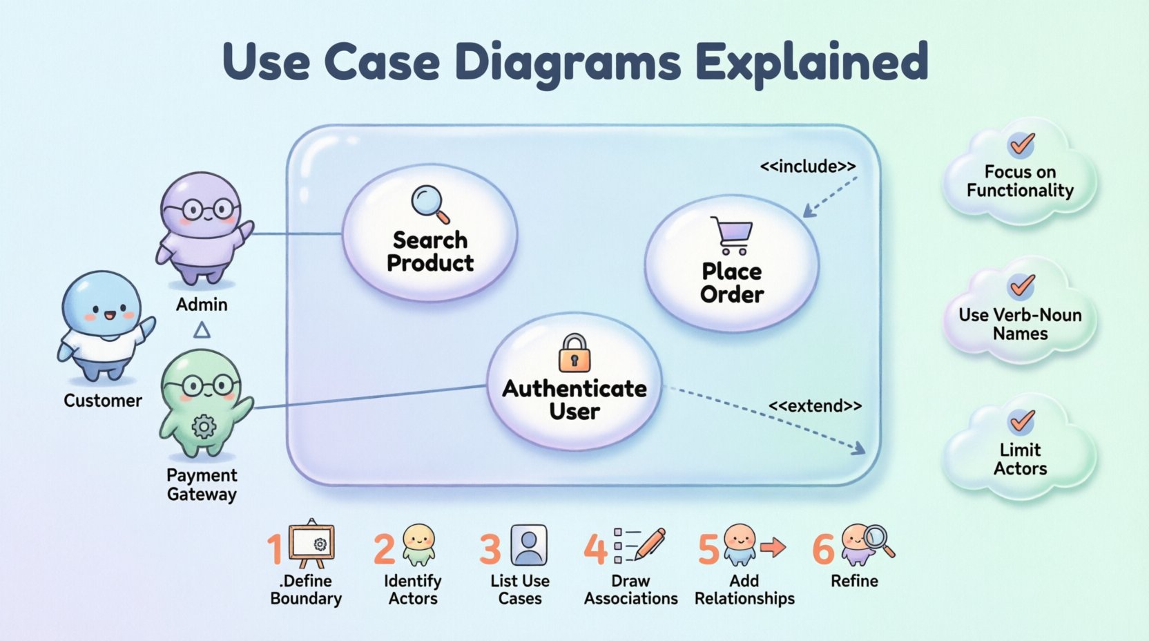
- Actors: Represent the users or external systems that interact with the software. They are depicted as stick figures.
- Use Cases: Represent specific functions or goals within the system. These are shown as ovals.
- System Boundary: A box that defines the scope of the system. Everything inside is part of the system; everything outside is external.
- Relationships: Lines connecting actors to use cases, and use cases to other use cases. These define the flow and dependencies.
🔢 Symbols and Notation Guide
Consistency in notation ensures that diagrams are readable across different teams and organizations. Below is a detailed table of the standard symbols used in UML Use Case Diagrams.
| Symbol | Name | Visual Description | Meaning |
|---|---|---|---|
| Stick Figure | Actor | A simple human-like figure | Represents a user or external system interacting with the main system. |
| Oval | Use Case | An oval shape containing text | Represents a specific function or goal within the system. |
| Rectangle | System Boundary | A large box enclosing use cases | Defines the limit of the system being modeled. |
| Solid Line | Association | A straight line connecting Actor and Use Case | Indicates that the actor can initiate or participate in the use case. |
| Dashed Line + <<include>> | Include Relationship | Arrow pointing from base to included, labeled include | The base use case always invokes the included use case. |
| Dashed Line + <<extend>> | Extend Relationship | Arrow pointing from extension to base, labeled extend | The extension adds behavior to the base use case under specific conditions. |
| Triangle Arrow | Generalization | Arrow with a hollow triangle head | Represents inheritance (e.g., a specific actor is a type of general actor). |
🔗 Understanding Relationships
The power of a Use Case Diagram lies in the relationships between its components. These connections dictate the flow of logic and the structure of the system requirements.
1. Association
The association relationship is the most basic link. It signifies that an actor initiates or interacts with a specific use case. For example, a Customer actor associates with the Place Order use case. This line indicates a direct communication path.
2. Include Relationship
An include relationship represents a mandatory behavior. When one use case includes another, it means the included use case is a required part of the base use case. This is useful for breaking down complex processes into reusable sub-processes.
- Example: The Withdraw Cash use case might include the Verify PIN use case. You cannot withdraw cash without verifying the PIN first.
- Direction: The arrow points from the base use case to the included use case.
3. Extend Relationship
An extend relationship represents optional or conditional behavior. The extended use case adds functionality to the base use case, but only under certain conditions. It allows for modeling exceptions or alternative flows without cluttering the main path.
- Example: The Place Order use case might be extended by Apply Discount. The discount applies only if the user has a membership.
- Direction: The arrow points from the extension use case to the base use case.
4. Generalization
Generalization allows for inheritance of behavior. It is used when one actor or use case is a specialized version of another. This helps reduce redundancy in the diagram.
- Actor Generalization: A Gold Member actor might be a specialization of a Registered User actor, inheriting the ability to view products but adding the ability to see exclusive deals.
- Use Case Generalization: A Pay Online use case might generalize both Pay via Credit Card and Pay via PayPal.
🛠️ How to Build a Use Case Diagram
Creating a robust diagram requires a structured approach. Following a logical process ensures that all functional requirements are captured accurately.
- Define the System Boundary: Draw a box representing the system. Clearly label it. Decide what is inside (the system) and what is outside (the environment).
- Identify the Actors: Determine who or what interacts with the system. Ask: “Who uses the system?” and “What external systems does this system talk to?” Name them clearly.
- List the Use Cases: Brainstorm the goals of the actors. What can they achieve? Write these as verbs followed by nouns (e.g., “Search Product”).
- Draw Associations: Connect actors to the use cases they interact with using solid lines.
- Add Relationships: Analyze the use cases for common behaviors. Use include for mandatory steps and extend for optional steps.
- Refine Generalizations: Check for duplicate actors or use cases that could be grouped into parent categories.
💡 Best Practices for Effective Modeling
While the rules of UML are strict, the art of modeling lies in applying them wisely. Adhering to best practices ensures your diagrams remain useful throughout the project lifecycle.
1. Focus on Functionality, Not Implementation
A common mistake is drawing implementation details. Do not include database operations, screen layouts, or specific code logic. The diagram should answer “What does the user get?” not “How is the data stored?”.
2. Maintain Granularity
Use cases should be of appropriate size. If a use case is too broad, it becomes vague. If it is too narrow, the diagram becomes cluttered. A good rule of thumb is that a use case should be achievable in a single session or represent a distinct business goal.
3. Use Active Voice for Naming
Always name use cases using a verb-noun structure. Instead of “Login,” use “Authenticate User.” Instead of “User Management,” use “Manage User Profile.” This makes the intent clear.
4. Limit Actor Complexity
Do not create too many actors. If an actor only interacts with one use case, it may not be necessary. Group similar actors where possible, or remove them if they do not add value to the system boundary.
5. Document the Pre- and Post-Conditions
While the diagram itself does not show conditions, the accompanying documentation should. Define what must be true before the use case starts (pre-condition) and what is true after it finishes (post-condition).
⚠️ Common Pitfalls to Avoid
Even experienced modelers can fall into traps. Being aware of these common errors can save time during reviews and development.
- Mixing Levels of Abstraction: Avoid mixing high-level business goals with low-level technical steps in the same diagram. Keep the view consistent.
- Confusing Actors with Users: An actor is a role, not a person. A single human can play multiple roles (e.g., a user can be both a “Buyer” and a “Reviewer”).
- Overusing Include/Extend: These relationships should not be used for every step. If a step is part of the main flow, it is usually just a part of the sequence, not an include. Use them for significant reusable or optional blocks.
- Ignoring the System Boundary: Ensure the box clearly separates internal processes from external interactions. If it is not inside the box, it is not part of the system.
- Creating Too Many Use Cases: A diagram with fifty use cases is often a sign of poor abstraction. Group functionality to maintain readability.
🔗 Integrating with Other UML Diagrams
A Use Case Diagram is rarely used in isolation. It serves as a foundation for more detailed technical designs.
- Sequence Diagrams: Once a use case is identified, a Sequence Diagram can detail the chronological interaction between objects to fulfill that use case.
- Class Diagrams: The objects involved in a use case often translate into classes in the system architecture.
- Activity Diagrams: For complex use cases, an Activity Diagram can map the workflow and decision points within that specific function.
By linking the Use Case Diagram to these other artifacts, you create a cohesive documentation set that guides the entire development process from requirement to code.
🧐 Frequently Asked Questions
Addressing common queries helps clarify the nuances of this modeling technique.
Q: Can a Use Case Diagram show non-functional requirements?
A: Not directly. Use Case Diagrams focus on functional behavior. Non-functional requirements (like performance or security) are usually documented in separate specifications or added as notes to the diagram.
Q: How many actors should a diagram have?
A: There is no strict limit, but typically a diagram should focus on the most significant roles. If you have more than five or six actors, consider splitting the diagram by subsystem or module.
Q: What is the difference between a Use Case and a Function?
A: A use case represents a complete goal from the user’s perspective. A function is a technical operation. A single use case might involve multiple functions or system calls.
Q: Do I need to show the internal logic of the use case?
A: No. The diagram shows the interaction, not the internal logic. Detailed logic belongs in the Use Case Specification or Sequence Diagram.
📝 Conclusion
Mastering the Use Case Diagram is about more than just drawing ovals and lines. It is about understanding the relationship between the system and its environment. By focusing on user goals and functional requirements, these diagrams provide a shared language for stakeholders and developers.
When constructed correctly, a Use Case Diagram reduces ambiguity, aligns business expectations with technical delivery, and serves as a reliable reference throughout the project. Remember to keep your diagrams clean, consistent, and focused on value. With practice, you will find that this tool becomes an indispensable part of your system design toolkit.
As you move forward with your own projects, apply the principles of clear actor definition, appropriate relationship usage, and strict adherence to the system boundary. These habits will ensure your documentation remains a valuable asset rather than a technical burden.