


Use Case Diagrams stand as a cornerstone of software engineering, specifically within the Unified Modeling Language (UML) framework. Despite their widespread adoption, a significant number of misconceptions surround their purpose, creation, and utility. Many practitioners treat them as mere documentation artifacts rather than functional specifications. This guide aims to strip away the confusion. We will explore the technical realities of modeling system behavior without the noise of marketing hype.
Understanding the distinction between a static diagram and a dynamic requirement is crucial for system architects and business analysts. When executed correctly, these diagrams clarify boundaries and interactions. When misunderstood, they lead to ambiguous specifications and development friction. The goal here is clarity, not persuasion.
📐 What is a Use Case Diagram?
A Use Case Diagram provides a visual representation of the functional requirements of a system. It focuses on what the system does from the perspective of external entities, rather than how it does it internally. This distinction is vital. It separates the behavior of the system from the implementation details.
- Scope: It defines the boundary of the system under consideration.
- Focus: It highlights the interactions between users (actors) and the system.
- Output: It serves as a high-level overview for stakeholders who may not need technical depth.
Unlike sequence diagrams or class diagrams, use case diagrams do not show the flow of control or the data structures. They show the services available to the user. This abstraction level is often where the confusion begins. Many assume the diagram describes the entire system logic, but it is strictly limited to user-initiated functionality.
👤 Understanding Actors
The term Actor is frequently misunderstood as referring solely to human users. In the context of UML, an actor represents any external entity that interacts with the system. This includes:
- Human Users: Administrators, customers, or employees.
- External Systems: Third-party APIs, legacy databases, or hardware devices.
- Timers: Automated processes that trigger actions at specific intervals.
- Networks: Communication channels that initiate requests.
When modeling, it is critical to categorize actors correctly. A generic “User” actor often leads to vague requirements. Specificity is required. For example, distinguishing between a Guest User and a Registered User clarifies permission levels early in the design phase. This granularity prevents scope creep later in the development lifecycle.
🎯 Defining Use Cases
A use case represents a specific goal achieved by an actor through interaction with the system. It is not a single screen or a button click. It is a complete task. For instance, “Place Order” is a use case. “Click Submit Button” is an action within a use case, not a use case itself.
Key characteristics of a well-defined use case include:
- Verb-Noun Naming: Examples include “Generate Report” or “Process Payment”.
- Atomic Goals: Each use case should achieve one distinct outcome.
- Actor Value: The actor must derive value from completing the use case.
If a use case cannot be completed by an actor without interacting with the system, it may not be a valid use case. It might be an internal process better suited for a sequence diagram. The use case must provide value to the actor, whether that value is information retrieval, data modification, or status notification.
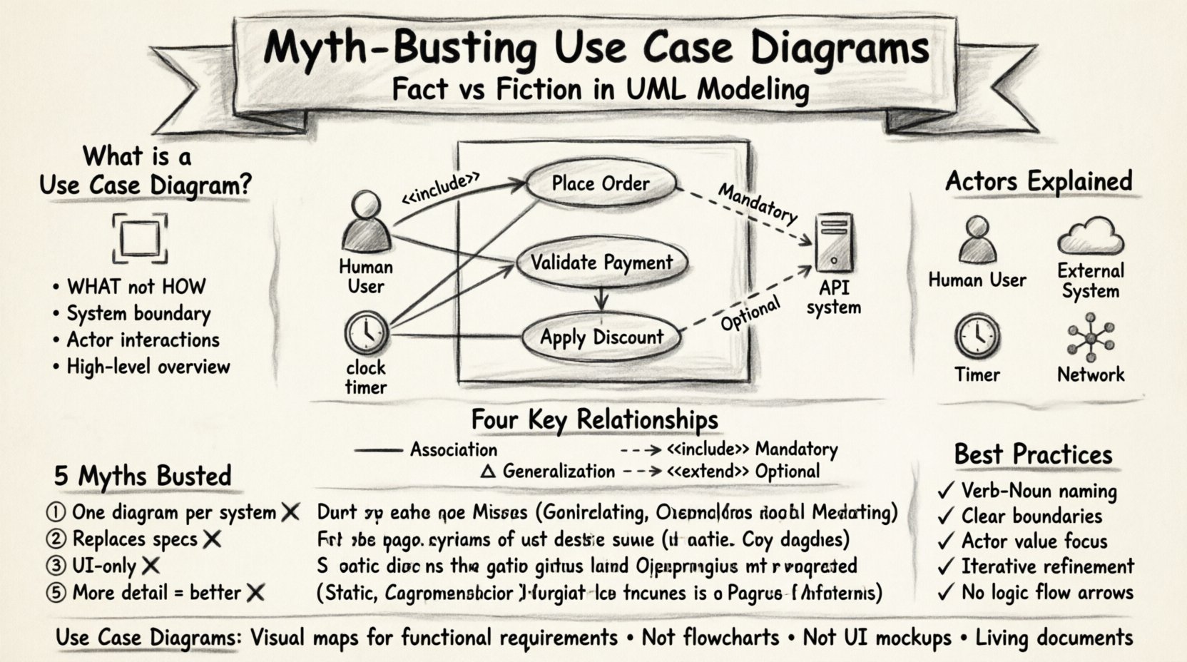
🔗 The Four Relationships
The relationships between actors and use cases, as well as between use cases themselves, define the structure of the system. Understanding these connections is the difference between a simple sketch and a functional specification. There are four primary relationship types in standard UML.
The following table outlines these relationships and their technical definitions.
| Relationship | Symbol | Definition | Usage Scenario |
|---|---|---|---|
| Association | Line | Connects actor to use case. | When an actor initiates a specific function. |
| Generalization | Triangle | Inheritance relationship. | One actor is a specialized version of another. |
| <<include>> | Dashed Arrow | Mandatory behavior. | A use case always requires another use case to complete. |
| <<extend>> | Dashed Arrow | Optional behavior. | A use case adds behavior under specific conditions. |
Association
This is the fundamental link. It indicates that an actor participates in a use case. It does not imply a specific direction of data flow. It simply states that interaction exists. If an actor cannot interact with a use case, the association line should not exist.
Generalization
Similar to object-oriented inheritance, this relationship allows for reuse of functionality. If a Gold Member actor can perform all actions of a Standard Member actor, they are related via generalization. This reduces redundancy in the diagram. It ensures that common behaviors are defined once and inherited by specific roles.
<<include>>
This relationship denotes mandatory inclusion. If Use Case A includes Use Case B, then Use Case B must happen for Use Case A to complete. A classic example is “Place Order” including “Validate Payment”. You cannot place an order without validating the payment method. The included use case is abstracted out to keep the main flow clean, but the requirement remains mandatory.
<<extend>>
This relationship denotes optional behavior. Use Case A extends Use Case B if it adds functionality only under specific conditions. For example, “Place Order” might be extended by “Apply Discount Code”. The discount is not required to complete the order, but it is available if the condition is met. This distinction between mandatory and optional is often overlooked, leading to rigid system designs.
🚫 Common Myths
Several persistent myths surround the creation and usage of Use Case Diagrams. Addressing these misconceptions helps in creating more accurate models.
Myth 1: One Diagram Per System
It is common to see attempts to draw a single diagram containing every function of a complex system. This leads to clutter and confusion. The reality is that use case diagrams should be modular. Different diagrams can represent different subsystems or different views for different stakeholders. A high-level diagram for management differs from a detailed diagram for developers.
Myth 2: They Replace Detailed Specifications
Some teams believe that a completed diagram eliminates the need for textual requirements. This is incorrect. The diagram provides a visual map, but the Use Case Specification documents the step-by-step logic, preconditions, postconditions, and error handling. The diagram shows the destination; the specification describes the journey.
Myth 3: They Are Only for UI Design
Because use cases often involve user interaction, many assume they only apply to graphical interfaces. However, they are equally valid for backend services, command-line interfaces, or API endpoints. Any system that accepts input and produces output can be modeled. Restricting them to UI limits their utility in modern service-oriented architectures.
Myth 4: They Are Static
A static diagram implies a lack of time or change. While the diagram itself is a snapshot, it represents dynamic behavior. It captures the intent of the system’s operation over time. It is not a flowchart, but it describes the capability to change state.
Myth 5: Too Detailed is Better
Adding excessive detail to a use case diagram often obscures the main functionality. If every sub-step is drawn as a separate box, the diagram becomes a flowchart. The abstraction level should remain consistent. If a use case becomes too complex, it should be broken down into a sub-diagram or a sequence diagram, not expanded on the main chart.
📋 Best Practices for Modeling
To ensure the diagrams remain effective tools rather than decorative elements, adhere to the following standards.
- Consistent Naming: Use a standard naming convention for all actors and use cases. Avoid abbreviations unless they are industry-standard.
- Clear Boundaries: Clearly define the system boundary box. Anything outside is an actor or external dependency.
- Focus on Value: Every use case must deliver value to an actor. If a function serves no actor, question its necessity.
- Iterative Refinement: Do not expect the first diagram to be perfect. Refine it as requirements evolve. Use case models are living documents.
- Avoid Logic Flow: Do not draw arrows that represent sequential logic flow (e.g., Step 1 to Step 2). Use arrows only for relationships like include or extend.
⚖️ When Not to Use Them
While powerful, use case diagrams are not a universal solution. There are scenarios where other modeling techniques are more appropriate.
- Complex Algorithms: If the focus is on mathematical logic or data transformation, a class diagram or activity diagram is better.
- Real-Time Systems: For systems where timing and concurrency are critical, state machine diagrams provide more precision.
- Simple CRUD: For simple Create, Read, Update, Delete applications, a list of requirements might be more efficient than a full diagram.
Recognizing when to use a specific tool is as important as knowing how to use it. Using a hammer for a screw is inefficient. Similarly, forcing a use case diagram onto a problem that requires state modeling creates unnecessary complexity.
🔍 Depth of Analysis
The true power of a use case diagram lies in the analysis it prompts. Before drawing lines, ask questions about the system. Who are the actors? What are their goals? What are the constraints? This inquiry phase is where the real engineering work happens. The drawing is merely the output of that thought process.
Consider the concept of Scope. A system might be a web portal, but the underlying service is an API. The actor might be a browser, but the real user is a human. Understanding the layers of abstraction prevents miscommunication between technical and non-technical teams. The diagram must reflect the correct layer of abstraction for its audience.
Furthermore, consider the Extensibility of the model. As new requirements emerge, the diagram should accommodate them without requiring a complete redraw. Using <<extend>> relationships effectively allows new features to be added as optional branches without disrupting the core flow. This supports agile development methodologies where requirements change frequently.
🛠️ Implementation Considerations
When implementing the logic described in these diagrams, developers often struggle with the mapping. A use case is not a function. It is a scenario. One function might serve multiple use cases. One use case might call multiple functions. This many-to-many relationship requires careful code architecture. The diagram does not dictate the code structure directly, but it informs the design of the service layer.
It is also important to note that use case diagrams do not specify the user interface. They specify the functionality. A “Search Product” use case could be implemented via a search bar, a voice command, or a CSV upload. The diagram remains valid regardless of the interface technology. This separation of concerns is a key benefit of the UML standard.
🔎 Final Thoughts on Accuracy
Accuracy in modeling is not about perfection; it is about fidelity to the requirements. A diagram that is slightly outdated is still more useful than a perfect one that was never created. The act of modeling forces the team to confront ambiguities in the requirements. If you cannot draw the line, you likely do not understand the requirement yet.
Therefore, the diagram is a diagnostic tool. It reveals gaps in logic, missing actors, or undefined boundaries. By treating the diagram as a living diagnostic rather than a finished product, teams can maintain higher quality standards throughout the project lifecycle. This approach shifts the focus from documentation to understanding.