


Creating clear and effective visual models is a cornerstone of robust system design. When stakeholders and developers look at a diagram, they need to understand the system’s functionality without ambiguity. A Use Case Diagram serves this purpose by capturing the interactions between actors and the system. However, creating these diagrams often leads to confusion if the underlying logic is not sound. This guide provides a structured approach to ensuring your diagrams are accurate, readable, and valuable.
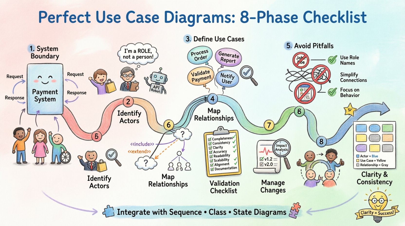
🛠️ Phase 1: Defining the System Boundary
Before drawing a single box or stick figure, you must establish the scope. The system boundary defines what is inside the system and what is outside. This distinction is critical because it determines which elements are part of the functional requirements and which are external influences.
- Identify the Core System: Clearly label the rectangle that represents the system. Avoid vague labels like “The System.” Use specific names, such as “Payment Processing Module” or “Inventory Management System.”
- Mark External Entities: Anything outside the rectangle is an actor or an external system. Ensure these are not drawn inside the boundary unless they are subsystems.
- Clarify Data Flow: While use case diagrams do not show data flow explicitly, the boundary implies where data enters and leaves the functional logic.
Without a clear boundary, actors may appear to interact with internal details rather than provided services. This leads to a model that is too detailed and difficult to maintain.
👥 Phase 2: Identifying Actors Correctly
Actors represent the roles played by people or systems that interact with the use case system. They are the initiators of actions or the recipients of outputs. Getting the actors right is often the most common source of error in diagramming.
What is an Actor?
An actor is a role, not necessarily a specific person. One human can play multiple roles, and one role can be played by multiple humans. For example, a “Manager” is an actor, not “John Smith.” Additionally, an actor can be another system, such as an external API or a legacy database.
- Primary Actors: These initiate the interaction to achieve a specific goal. They are the users of the system.
- Secondary Actors: These are systems or services that the main system interacts with to complete a task. They provide data or services but do not initiate the use case.
- Generic vs. Specific: Avoid listing specific individuals. Use role-based names like “Customer,” “Admin,” or “Third-Party Service.”
Common Actor Mistakes
| Incorrect Approach | Correct Approach |
|---|---|
| Labeling “John Doe” | Labeling “Registered User” |
| Placing actors inside the system boundary | Placing actors outside the system boundary |
| Creating actors for every screen | Creating actors for functional roles |
| Forgetting system-to-system actors | Including external APIs as actors |
By adhering to role-based naming and correct placement, the diagram remains stable even if personnel change.
🎯 Phase 3: Defining Use Cases
A use case represents a complete unit of functionality that provides value to an actor. It is not a single action but a sequence of actions that achieves a goal. The naming convention for use cases is vital for clarity.
Naming Conventions
Use case names should be verb phrases that describe the action from the actor’s perspective. They should be concise but descriptive enough to stand alone.
- Verb-Object Format: Examples include “Process Order,” “Generate Report,” or “Update Profile.” Avoid nouns like “Order Processing” unless it refers to a specific document rather than an action.
- Goal-Oriented: Ask yourself, “What does the actor want to achieve?” If the answer is “To pay the bill,” the use case is “Pay Bill,” not “Pay Bill Screen.”
- Scope Consistency: Ensure all use cases are at the same level of abstraction. Do not mix high-level goals (“Manage Account”) with low-level steps (“Enter Password”).
Granularity Check
If a use case is too broad, it becomes vague. If it is too narrow, it creates clutter. A good rule of thumb is that a use case should be performable by an actor in a single session or represent a distinct business transaction. Complex workflows should be broken down into smaller use cases linked by relationships.
🔗 Phase 4: Mapping Relationships
The power of a use case diagram lies in the relationships between actors and use cases, and between use cases themselves. These lines convey the logic of the system.
Association
The solid line connecting an actor to a use case indicates that the actor interacts with that functionality. Every actor should have at least one association, and every use case should have at least one actor.
- Directionality: While often drawn bidirectional, the logical flow usually starts from the actor initiating the request.
- Multiple Actors: A single use case can be linked to multiple actors. For instance, “View Report” might be linked to “Manager” and “Auditor.”
Include Relationship
An include relationship indicates that one use case always incorporates the behavior of another. The included use case is necessary for the base use case to complete its goal. Think of this as a subroutine.
- When to Use: Use this for common functionality shared across multiple use cases. For example, “Authenticate User” might be included in “Login,” “Reset Password,” and “Change Credentials.”
- Notation: Typically shown as a dashed arrow with the label “<<include>>” pointing from the base use case to the included one.
Extend Relationship
An extend relationship indicates optional behavior. The extending use case adds functionality to the base use case under specific conditions. This is useful for error handling or optional features.
- When to Use: Use this for exceptions or variations. For example, “Send Notification” might extend “Place Order” only if the payment fails.
- Conditionality: Always define the extension point or condition clearly. The base use case works without the extension.
Generalization
Generalization is used for inheritance. A specialized actor or use case inherits the behavior of a generalized one. This reduces redundancy in the diagram.
- Actor Inheritance: If “Premium User” inherits from “Registered User,” you do not need to draw all associations for “Registered User” again.
- Use Case Inheritance: If “Generate Monthly Report” is a specific type of “Generate Report,” you can use generalization to show the hierarchy.
🚫 Phase 5: Avoiding Common Pitfalls
Even experienced modelers make mistakes. Below is a checklist of common errors and how to resolve them to ensure diagram quality.
| Pitfall | Impact | Solution |
|---|---|---|
| Overlapping Actors | Confusion on who does what | Separate actors clearly; use generalization if roles are similar |
| Circular Dependencies | Logical loops that break flow | Review include/extend logic; ensure base use cases are self-contained |
| Too Many Relationships | Diagram becomes unreadable | Consolidate common behaviors; use notes for detailed logic |
| Missing Actors | Incomplete system view | Review all functional requirements; ensure every use case has an initiator |
| Interface Confusion | Mixing UI with logic | Keep diagrams focused on functionality, not screen layout |
| Unused Use Cases | Dead code in the model | Review periodically; remove use cases with no actors or dependencies |
🔍 Phase 6: The Validation Checklist
Before finalizing the diagram, run through this validation list. This ensures the model is robust and ready for development teams.
- Completeness: Does every use case have at least one actor?
- Consistency: Are all actor names consistent with the glossary?
- Clarity: Is the system boundary clearly labeled?
- Accuracy: Do the relationships (include/extend) logically match the requirements?
- Readability: Is the layout clean? Do lines cross unnecessarily?
- Scalability: Can new use cases be added without breaking the existing structure?
- Alignment: Does the diagram align with the high-level business goals?
- Documentation: Are complex use cases documented with notes or descriptions?
🔄 Phase 7: Managing Changes Over Time
Requirements evolve. Software is rarely static. A use case diagram must be treated as a living document that reflects the current state of the system. Maintaining this document is as important as creating it.
Version Control
Keep track of changes. When a use case is added, modified, or removed, update the diagram version. This helps in auditing and understanding the evolution of the system.
Impact Analysis
When a requirement changes, analyze how it affects the diagram. If a new actor is introduced, check if existing use cases need to be modified. If a use case is removed, ensure no other use cases depend on it via an include relationship.
Stakeholder Review
Regularly review the diagram with stakeholders. They can identify if the model still matches their mental model of the system. This feedback loop ensures the diagram remains relevant.
📏 Phase 8: Ensuring Clarity and Consistency
Visual consistency aids comprehension. If the diagram looks messy, the logic behind it might be perceived as messy.
- Alignment: Align actors and use cases. Use grid lines or spacing to create a structured layout.
- Color Usage: While avoiding CSS styles is required for raw HTML, in actual modeling tools, consider using color to distinguish between primary and secondary actors, or to highlight deprecated use cases.
- Labels: Ensure all labels are legible. Avoid abbreviations unless they are standard industry terms.
- Spacing: Leave enough space around elements to prevent lines from overlapping text.
🧩 Integrating with Other Models
A use case diagram is rarely used in isolation. It works best when integrated with other modeling techniques.
- Sequence Diagrams: Use sequence diagrams to detail the interaction flow within a specific use case.
- Class Diagrams: Use class diagrams to define the objects involved in the use cases.
- State Diagrams: Use state diagrams to show the lifecycle of an object involved in a use case.
By linking these models, you create a comprehensive view of the system without cluttering the use case diagram itself. The use case diagram remains the entry point for understanding functionality, while other diagrams provide the implementation details.
🏁 Final Review Steps
Before distributing the diagram, perform a final sanity check.
- Read every label aloud to ensure it makes sense grammatically.
- Verify that no actor is isolated without a connection.
- Check that include/extend relationships are not used interchangeably.
- Ensure the system boundary encompasses all intended functionality.
- Confirm that the diagram fits on a single page or is paginated logically.
Following this structured checklist ensures that your diagrams are not just pictures, but functional tools for communication. They bridge the gap between business needs and technical implementation. By focusing on roles, goals, and relationships, you create models that stand the test of time and change.
Remember, the goal is clarity. If a stakeholder can look at the diagram and understand what the system does, you have succeeded. Keep the focus on value, keep the structure logical, and maintain the diagram as requirements evolve.