


Software engineering involves more than just writing code. It requires the ability to model systems, understand requirements, and communicate complex logic to diverse stakeholders. Among the various modeling techniques available, the Use Case Diagram stands out as a fundamental tool for capturing functional requirements. For engineers entering the field, mastering this skill provides a significant advantage in system design and documentation.
This guide explores the core competencies required to create effective Use Case Diagrams. We will examine the structural elements, relationships, and best practices that define a robust diagram. By focusing on the underlying principles rather than specific tools, you can apply these skills across any project environment.
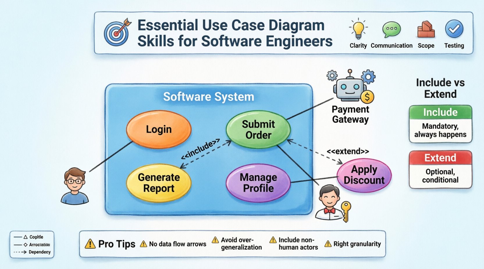
Understanding the Core Purpose 🎯
A Use Case Diagram serves as a high-level map of system functionality. It visualizes how users, known as actors, interact with the system to achieve specific goals. Unlike detailed flowcharts that describe the step-by-step logic of a process, Use Case Diagrams focus on the what rather than the how.
Why is this distinction important? When you are in the early stages of development, stakeholders care about capabilities. They want to know if the system can process a payment, generate a report, or manage a user profile. They do not need to see the SQL queries or the conditional branching logic at this stage. The diagram bridges the gap between business needs and technical implementation.
Key Benefits for Engineers
- Clarity: Reduces ambiguity in requirements by visualizing interactions.
- Communication: Provides a common language for developers, testers, and product managers.
- Scope Definition: Helps identify what is inside and outside the system boundaries.
- Test Planning: Forms the basis for functional testing scenarios.
Foundational Elements of UML Use Cases 🧱
To draw a meaningful diagram, you must understand the specific notation used. These elements remain consistent regardless of the software used to create the image.
1. Actors 🧍♂️
An actor represents a role that interacts with the system. It does not necessarily refer to a specific person. An actor can be:
- A human user (e.g., Administrator, Customer).
- An external system (e.g., Payment Gateway, Inventory Database).
- A hardware device (e.g., Sensor, Printer).
Actors are typically drawn as stick figures. The key skill here is role abstraction. You should avoid naming specific individuals (like “John”) and instead use functional roles (like “Account Holder”). This ensures the diagram remains valid even if personnel changes.
2. Use Cases 🔄
A use case represents a specific goal or function that the system performs. It is drawn as an ellipse. Each use case describes a complete unit of functionality.
- Granularity: A use case should be atomic. If a function involves multiple distinct goals, it may need to be split into separate use cases.
- Naming: Use case names should follow a verb-noun structure (e.g., “Submit Order” rather than “Order”).
- Scope: They must fall within the system boundary.
3. System Boundary 📦
The system boundary is a rectangle that encloses all use cases. It clearly defines the perimeter of the software.
- Everything inside the box is part of the system.
- Everything outside the box is part of the environment.
- Actors reside outside the box, connecting to the use cases inside via lines.
Defining this boundary is a critical skill. If a use case is placed outside, it implies the system does not perform that function. If it is placed inside, the system is responsible for it. Ambiguity here leads to scope creep later in the project.
Relationships and Interactions 🕸️
The power of a Use Case Diagram lies in how elements relate to one another. There are four primary relationship types you must master.
Association 📏
This is a solid line connecting an actor to a use case. It indicates that the actor initiates or participates in that specific function.
- Direction: While often drawn without arrows, the interaction usually flows from the actor to the system.
- Multiple Actors: A single use case can be associated with multiple actors.
- Multiple Use Cases: A single actor can be associated with multiple use cases.
Generalization 🌳
This relationship allows for inheritance. It is drawn as a solid line with a hollow triangle arrow pointing toward the parent.
- Actor Generalization: A specialized actor inherits the capabilities of a generalized actor. For example, a “Registered User” is a specialization of “User”. The “Registered User” can do everything a “User” can do, plus specific features.
- Use Case Generalization: A specific use case can inherit behavior from a more general use case.
Include 🔗
The Include relationship represents mandatory behavior. It indicates that one use case explicitly invokes the functionality of another use case.
- Notation: Dashed line with an arrow labeled <<include>> pointing to the included use case.
- Usage: Use this when a step is required in every instance of the parent use case. For example, “Login” might be included in “Place Order”. You cannot place an order without logging in.
- Benefit: Reduces redundancy by defining common steps once.
Extend 🔗
The Extend relationship represents optional behavior. It indicates that one use case adds functionality to another under specific conditions.
- Notation: Dashed line with an arrow labeled <<extend>> pointing to the base use case.
- Usage: Use this for optional steps or error handling. For example, “Apply Discount Code” extends “Place Order”. The discount is not always applied.
- Trigger: The extension occurs only if a specific condition is met.
Comparing Include vs. Extend 📊
| Feature | Include | Extend |
|---|---|---|
| Requirement | Mandatory | Optional |
| Dependency | Base depends on Included | Extension depends on Base |
| Flow | Always happens | Happens under specific conditions |
| Direction | Arrow points to Included | Arrow points to Base |
Designing for Clarity and Readability ✨
Creating a diagram is not enough; it must be readable. A cluttered diagram fails to communicate. Here are strategies to maintain clarity.
Grouping Use Cases
When a system has many functions, grouping them can help. You might use sub-systems or packages to categorize related use cases (e.g., “Reporting Module”, “User Management Module”). This reduces visual noise.
Limiting the Scope
Do not try to diagram the entire enterprise in one image. Focus on a specific subsystem or a specific release. If a diagram becomes too large, it becomes unreadable. Split the model into multiple diagrams linked by references.
Consistent Naming Conventions
Ensure all actors and use cases follow a consistent naming style. If you use “Submit Form” in one area, do not use “Enter Data” in another. Consistency aids in quick comprehension.
Common Pitfalls to Avoid ⚠️
Even experienced engineers make mistakes. Being aware of common errors helps you refine your skills.
1. Mixing Data Flow with Use Cases
Use Case Diagrams do not show data flow or internal processing. Avoid drawing arrows between use cases unless they represent an Include or Extend relationship. Do not show the flow of data between actors and the database.
2. Overusing Generalization
While inheritance is powerful, overusing it can create confusion. If the relationship is not strictly hierarchical, use Association instead. Not every similarity requires a Generalization relationship.
3. Ignoring Non-Human Actors
Software often interacts with other systems. If you only draw human actors, you miss critical integrations. Always consider external APIs, third-party services, or automated scripts as actors.
4. Creating Atomic or Too Complex Use Cases
If a use case name is “Manage System”, it is too broad. Break it down. If a use case is “Click Button 1, then Type Text, then Press Enter”, it is too detailed. Aim for the level of functionality visible to the actor.
Integration into the Development Lifecycle 🔄
Use Case Diagrams are not static documents. They evolve as the project progresses. Here is how they fit into different phases.
Requirement Gathering
During the initial phase, these diagrams capture the high-level needs. They serve as a checklist for stakeholders to verify that their needs are understood.
Design Phase
Developers use the diagrams to identify which classes and methods are needed. Each use case often translates to a specific service or controller in the architecture.
Testing Phase
Testers derive test cases directly from the use cases. Each use case represents a potential test scenario. This ensures 100% coverage of functional requirements.
Maintenance Phase
When changes are requested, the diagram is updated to reflect new functionality. This helps in impact analysis, determining which parts of the system might be affected by a change.
Advanced Techniques for Complex Systems 🧩
As systems grow, simple diagrams may not suffice. Here are techniques to handle complexity.
Use Case Inclusion Patterns
For complex systems, you may need to define common behaviors like “Authentication” or “Logging”. Define these as separate use cases and include them in multiple parent use cases. This ensures consistency across the system.
System Context Diagrams
Before diving into detailed use cases, create a system context diagram. This shows the entire system as a single bubble interacting with external actors. It provides a macro view before zooming into the micro details.
Interaction with Sequence Diagrams
Use Case Diagrams show the what. Sequence Diagrams show the how. For critical use cases, link them to detailed sequence diagrams. This provides a complete picture of the system behavior without overcrowding the Use Case Diagram.
Communication and Collaboration Skills 🤝
Drawing the diagram is only half the battle. You must also be able to present and defend it.
Presenting to Stakeholders
When showing the diagram to non-technical stakeholders, focus on the value. Explain how each use case meets a business goal. Avoid getting bogged down in notation details unless they ask.
Collaborating with Developers
When working with developers, ensure the diagram aligns with the technical constraints. If a use case requires a capability the technology stack cannot support, update the diagram or the plan immediately.
Iterative Refinement
Do not expect the first version to be perfect. Use Case Diagrams are living documents. As you learn more about the system, refine the actors and relationships. This iterative approach ensures accuracy.
Practical Steps to Create a Diagram 📝
Follow this workflow to build a diagram from scratch.
- Identify the System: Define the boundary. What is being built?
- List the Actors: Who or what interacts with the system?
- Define the Goals: What does each actor want to achieve?
- Map the Interactions: Draw lines connecting actors to their goals.
- Refine Relationships: Add Include, Extend, or Generalization where appropriate.
- Review and Validate: Check for completeness and consistency.
Conclusion on Professional Growth 📈
Proficiency in Use Case Diagrams is a marker of a well-rounded software engineer. It demonstrates that you can think beyond code and understand the broader context of software delivery. By mastering the notation, relationships, and communication aspects, you ensure that your designs are clear, maintainable, and aligned with business needs.
Continue to practice these skills on various projects. Whether the system is small or large, the principles remain the same. Focus on clarity, accuracy, and the value of the model to the team.