


Model-Based Systems Engineering (MBSE) shifts the focus from static documentation to dynamic, executable models. At the core of this methodology lies SysML, the Systems Modeling Language. While the language provides a robust set of constructs, the value is only realized when the models are consistent, readable, and maintainable across a large team. Inconsistent modeling leads to ambiguity, broken traceability, and increased validation costs. This guide outlines the structural and behavioral standards recommended by experienced practitioners to ensure high-quality SysML artifacts.
Consistency is not merely about aesthetics; it is about semantic integrity. When a modeler adds a new component or defines a requirement, the impact ripples through the entire system. Adhering to established patterns reduces cognitive load for reviewers and facilitates automated analysis. The following sections detail the critical areas of focus for any MBSE initiative.
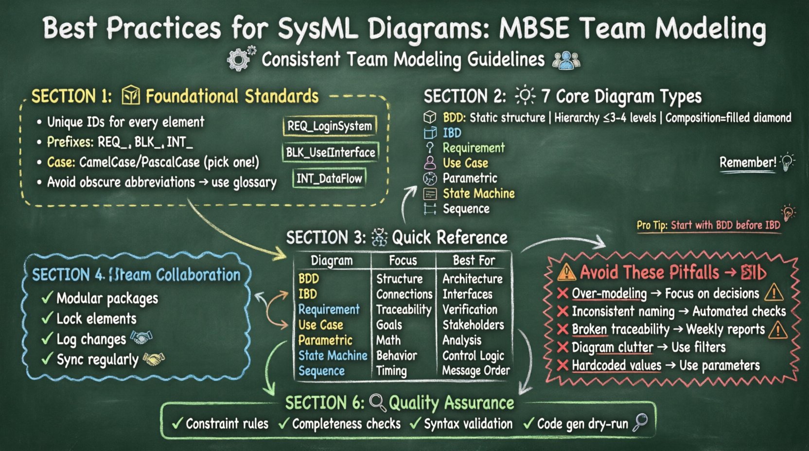
🏗️ Foundational Standards: Naming and Identification
Before drawing a single line, the team must agree on the nomenclature rules. Ambiguous names are the root cause of many modeling errors. A name should be descriptive enough to understand the element’s purpose without referring to the diagram context.
- Unique Identifiers: Every element must have a unique internal identifier. This is often handled automatically by the platform, but external references should use these IDs rather than names to avoid breakage during renaming.
- Prefixes and Suffixes: Use prefixes to denote domain or subsystem. For example,
REQ_for requirements,BLK_for blocks, andINT_for interfaces. This allows for quick filtering and sorting within the model tree. - Case Sensitivity: Decide on a standard for capitalization. CamelCase or PascalCase is common. Consistency is more important than the specific choice. Stick to one pattern for all elements.
- Abbreviations: Avoid obscure acronyms. If an abbreviation is necessary, define it in the model glossary. This ensures that new team members can understand the terminology without external documentation.
When naming elements, think about the search functionality. A name like Control_Unit is less effective than Flight_Control_Unit if the system is a spacecraft. Contextual precision aids in query performance and reduces the likelihood of duplicate elements.
🧩 Core Diagram Types and Specific Guidelines
SysML offers nine diagram types. Not all are used equally, but the most common ones require specific attention to structure and content. Below is a breakdown of the primary diagrams and the best practices associated with each.
1. Block Definition Diagram (BDD)
The BDD defines the static structure of the system. It is the backbone of the model. Poorly constructed BDDs result in unclear hierarchies and difficult-to-manage inheritance.
- Hierarchy Management: Keep the depth of decomposition logical. Avoid nesting blocks deeper than three or four levels unless necessary. Deep nesting makes navigation difficult.
- Composition vs. Association: Use composition (filled diamond) when the part cannot exist without the whole (e.g., a wing on a plane). Use association (open diamond or line) for optional relationships.
- Refinement Blocks: Do not use refinement relationships for simple inheritance. Use generalization (parent-child relationship) for taxonomy.
- Interface Usage: Define interfaces as blocks and use usage relationships to show implementation. Do not place interface definitions directly on blocks without a clear contract.
2. Internal Block Diagram (IBD)
IBDs describe the internal structure of a block, showing how parts interact. This is often where the most detailed engineering logic resides.
- Ports vs. Parts: Use parts to represent physical components. Use ports to represent interaction points. Do not use parts for connections; parts are the things, ports are the places where things connect.
- Flow Directions: Clearly indicate the direction of data, power, or physical flow using arrows. This helps in identifying potential bottlenecks or missing power paths.
- Value Properties: Use value properties to define parameters like mass, voltage, or data rate. Ensure units are defined and consistent across the model.
- Subsystems: When an IBD becomes too complex, introduce a subsystem block and reference it. This allows for a high-level view without cluttering the main diagram.
3. Requirement Diagram
This diagram manages the system requirements and their relationships. It is critical for verification and validation.
- Traceability: Every requirement should trace to a source (e.g., a stakeholder need) and to the system elements that satisfy it. Broken trace chains are a major red flag during audits.
- Constraint Satisfaction: Use the
refineandsatisfyrelationships correctly. Do not mix them up.Satisfylinks requirements to blocks.Refinelinks requirements to other requirements. - Versioning: Requirements change. Ensure the model tracks version history. Use comments or properties to indicate the maturity level (e.g., Draft, Baseline, Verified).
4. Use Case Diagram
Use cases describe the functional behavior of the system from the perspective of the user or actor.
- Actor Definition: Define actors as people, organizations, or external systems. Do not define internal components as actors unless they are interacting from outside the system boundary.
- Use Case Granularity: Keep use cases at a consistent level of abstraction. Mixing high-level goals with low-level steps confuses the scope.
- Include vs. Extend: Use
includefor mandatory behavior shared by multiple use cases. Useextendfor optional behavior that occurs under specific conditions.
5. Parametric Diagram
Parametric diagrams link constraints to specific values, allowing for mathematical analysis and sizing.
- Constraint Blocks: Define constraint blocks for reusable equations. Avoid hard-coding equations directly on the diagram.
- Equation Validation: Ensure that units are compatible. Mixing meters and feet in the same constraint block causes calculation errors.
- Solver Setup: Define which properties are inputs and which are outputs. This ensures the model solver can find a solution without ambiguity.
6. State Machine Diagram
These diagrams model the behavior of a system over time, reacting to events.
- Initial and Final States: Every state machine must have a clear entry point and exit points. Avoid orphaned states that cannot be reached.
- Transition Guarding: Use guards on transitions to prevent unintended state changes. A transition without a guard fires immediately upon event occurrence.
- Activity vs. State: Use state machines for control flow. Do not use them for data processing logic unless the processing is state-dependent.
7. Sequence Diagram
Sequence diagrams show the interaction between objects over time.
- Lifelines: Ensure lifelines match the blocks in the BDD. Do not create new lifelines that do not exist in the structural model.
- Messages: Distinguish between synchronous and asynchronous messages. Synchronous messages wait for a response; asynchronous messages do not.
- Fragment Types: Use
altfor alternatives andoptfor optional fragments. Keep the nesting depth of fragments shallow to maintain readability.
📊 Comparison of Diagram Purposes
To ensure the right tool is used for the right job, refer to the following matrix.
| Diagram Type | Primary Focus | Key Elements | Best Used For |
|---|---|---|---|
| Block Definition Diagram | Static Structure | Blocks, Associations | System Architecture Definition |
| Internal Block Diagram | Internal Connections | Parts, Ports, Flows | Interface and Data Flow Definition |
| Requirement Diagram | Requirements | Requirements, Relations | Traceability and Verification |
| Use Case Diagram | Functional Goals | Actors, Use Cases | Stakeholder Interaction |
| Parametric Diagram | Mathematical Constraints | Constraints, Variables | Sizing and Performance Analysis |
| State Machine Diagram | Behavioral States | States, Transitions | Control Logic and Modes |
| Sequence Diagram | Interaction Flow | Lifelines, Messages | Message Timing and Order |
🤝 Collaboration and Version Control
In a team environment, multiple engineers often work on the same model simultaneously. This introduces the risk of merge conflicts and data loss. A robust workflow is essential.
- Modular Modeling: Split the model into logical packages. Each engineer should own a specific package or subsystem. This reduces the surface area for conflicts.
- Locking Mechanisms: Use locking features in the modeling tool to prevent simultaneous edits on the same element. If the tool does not support this, establish a manual check-in process.
- Change Logs: Every modification should be logged. Document the reason for the change, the author, and the date. This is vital for audit trails.
- Regular Syncs: Schedule daily or weekly synchronization sessions. Do not wait until the end of a sprint to merge changes.
⚠️ Common Pitfalls and How to Avoid Them
Even experienced modelers make mistakes. Recognizing common patterns of error helps in preventing them.
| Pitfall | Impact | Mitigation Strategy |
|---|---|---|
| Over-Modeling | Unnecessary complexity and maintenance overhead | Focus on the information needed for decision-making. Do not model for the sake of modeling. |
| Inconsistent Naming | Confusion and search failures | Enforce naming standards through automated checks or pre-commit hooks. |
| Broken Traceability | Inability to verify requirements | Run traceability reports weekly. Ensure every requirement has at least one linked element. |
| Diagram Clutter | Reduced readability | Use diagrams to show specific views. Hide unnecessary elements using filters or layers. |
| Hardcoded Values | Model inflexibility | Use parameters and properties for all variable values. Make the model configurable. |
🔍 Model Validation and Quality Assurance
Automated validation is a powerful tool for maintaining model health. Most modeling environments allow for the definition of consistency rules.
- Constraint Checking: Define rules that prevent invalid relationships. For example, a block cannot be connected to itself in a composition.
- Completeness Checks: Verify that all defined requirements have corresponding design elements. This ensures no requirement is left behind.
- Syntax Validation: Run syntax checks to ensure proper grammar usage. This catches errors before the model is shared.
- Code Generation: If the model is used for code generation, run a dry run periodically. This ensures the model is syntactically correct for the target language.
🚀 Moving Forward with Model Integrity
Sustaining high-quality SysML models requires ongoing discipline. The standards defined here should not be static; they must evolve as the project matures. Regular retrospectives on the modeling process can identify areas where the standards are hindering progress or failing to provide value.
Training is equally important. Team members should be proficient in the specific dialect and extensions used by the organization. A shared understanding of the language ensures that the model communicates intent clearly across the engineering lifecycle.
Ultimately, the goal is to create a model that serves as a single source of truth. When the model is reliable, engineers can trust it for analysis, simulation, and documentation. This trust reduces risk and accelerates the path to a successful system delivery.