


Welcome to this comprehensive guide on Systems Modeling Language (SysML). Whether you are a systems engineer, a software architect, or a student entering the field of complex system design, understanding behavioral modeling is essential. This tutorial focuses on two of the most critical diagram types: Interaction Diagrams and State Machine Diagrams. We will explore their purpose, structure, and how to construct them from scratch without relying on specific proprietary tools.
Introduction to SysML and Behavioral Modeling 🚀
Systems Modeling Language is a general-purpose modeling language for systems engineering applications. It is based on the Unified Modeling Language (UML) but tailored to address the broader scope of systems engineering. While UML focuses heavily on software, SysML integrates structure, behavior, requirements, and constraints.
Behavioral modeling is a core component of SysML. It describes how a system changes over time in response to stimuli. There are two primary ways to represent behavior in SysML:
- Interaction Diagrams: Focus on the flow of messages between objects over time.
- State Machine Diagrams: Focus on the lifecycle of a single object and how it reacts to events.
Understanding when to use each type is the first step in effective modeling. Interaction diagrams are best for complex sequences involving multiple participants. State machine diagrams are ideal for defining the internal logic of a specific component.
Understanding Interaction Diagrams 💬
Interaction diagrams depict the exchange of messages between objects. They are temporal, meaning they show events in a specific sequence. In SysML, the primary interaction diagrams are the Block Definition Diagram (BDD) context and the Internal Block Diagram (IBD) context, but the specific behavioral view is often the Sequence Diagram or Communication Diagram.
For this tutorial, we will focus on the sequence of interactions, often visualized as a sequence diagram.
Key Components of Interaction Diagrams
- Lifelines: Vertical lines representing the existence of an object over time.
- Messages: Arrows indicating the flow of information or commands between lifelines.
- Activation Bars: Rectangular boxes on lifelines showing when an object is actively performing an action.
- Combined Fragments: Boxes that define how message sequences are handled (e.g., loops, options).
When to Use Interaction Diagrams
| Scenario | Diagram Type |
|---|---|
| System starts up and sends data to a database | Interaction Diagram |
| Handling a specific error state in a module | State Machine Diagram |
| Multiple subsystems communicating simultaneously | Interaction Diagram |
| Defining the lifecycle of a single sensor | State Machine Diagram |
Step-by-Step: Building Your First Interaction Diagram 📝
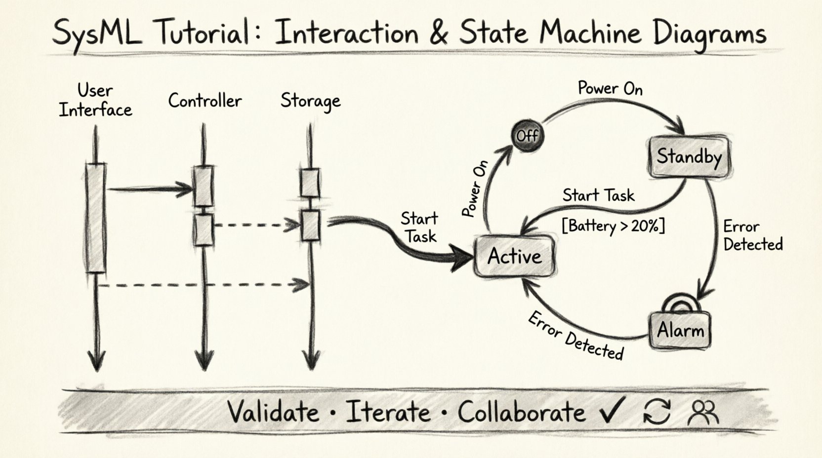
Let us construct a simple interaction diagram for a generic system. Imagine a system where a user requests data, a controller processes it, and a storage unit saves it.
Step 1: Define the Participants (Lifelines)
First, identify the objects involved. In SysML, these are typically represented as Blocks. For our example:
- User Interface Block: The entry point for the request.
- Controller Block: The logic processor.
- Storage Block: The data repository.
Draw a vertical line for each block. Label the top of the line with the Block name. This is your lifeline.
Step 2: Define the Messages
Messages represent the interaction. They flow from the sender’s lifeline to the receiver’s lifeline.
- Request Data: Draw an arrow from the User Interface to the Controller. Label it “Request Data”.
- Process Data: Draw an arrow from the Controller to the Storage Block. Label it “Fetch Record”.
- Return Result: Draw a dashed arrow from the Storage Block back to the Controller. Label it “Data Response”.
- Display: Draw a dashed arrow from the Controller back to the User Interface. Label it “Show Result”.
Step 3: Add Activation Bars
Activation bars indicate the period during which the object is performing an action. Place a thin rectangle on the lifeline where the object is active.
- Place an activation bar on the Controller lifeline starting when “Request Data” arrives.
- Place an activation bar on the Storage Block lifeline starting when “Fetch Record” arrives.
- Extend the Controller activation bar until “Show Result” is sent.
Step 4: Refine with Time
Interaction diagrams are time-sensitive. Ensure that messages are ordered vertically. The top of the diagram represents the earliest time, and the bottom represents the latest time. If two messages occur simultaneously, they should be at the same horizontal level.
Deep Dive: State Machine Diagrams ⚙️
While interaction diagrams show how objects talk to each other, State Machine Diagrams show how an object thinks. They describe the different states an object can be in and the transitions between those states.
Core Concepts of State Machines
- State: A condition during the life of an object during which it satisfies some condition, performs some activity, or waits for some event.
- Transition: The movement from one state to another. This is triggered by an event.
- Event: Something that happens at a specific point in time that triggers a transition.
- Guard Condition: A boolean expression that must be true for a transition to occur.
- Initial State: The starting point of the state machine (usually a solid black circle).
- Final State: The ending point of the state machine (usually a black circle with a ring).
Why Use State Machines?
State machines are crucial for systems that have distinct modes of operation. For example, a battery-powered device might have states like “Charging”, “Discharging”, and “Sleeping”. The behavior of the device changes depending on which state it is in.
Step-by-Step: Constructing a State Machine Diagram 🛠️
Let us build a state machine for a generic “Power Management System”.
Step 1: Define the States
Identify the distinct modes of operation. For our power system:
- Off: System is powered down.
- Standby: System is ready but not fully active.
- Active: System is performing its main function.
- Alarm: An error or warning condition exists.
Draw a rounded rectangle for each state. Write the name inside.
Step 2: Define the Transitions
Transitions connect states. They are represented by arrows. Label the arrow with the event that triggers the change.
- Off to Standby: Event: “Power On”.
- Standby to Active: Event: “Start Task”.
- Active to Standby: Event: “Pause Task”.
- Active to Alarm: Event: “Error Detected”.
- Alarm to Standby: Event: “Reset System”.
Step 3: Add Initial and Final States
Every state machine must start somewhere. Draw a solid black circle and connect it with an arrow to the “Standby” state (assuming the system boots into standby). Label this transition “Boot”.
Define an end state. If the system shuts down completely, connect a state to a black circle with a ring. Label this “Shutdown”.
Step 4: Incorporate Guard Conditions
Not all transitions should happen automatically. Sometimes, a condition must be met. For example, moving from “Standby” to “Active” might require a battery level check.
- Add a guard condition to the “Standby to Active” transition.
- Label it: [Battery Level > 20%].
- If the battery is low, the transition cannot occur, and the system remains in Standby.
Step 5: Add Entry and Exit Actions
Actions can be performed when entering or leaving a state.
- Entry Action: Action performed immediately upon entering the state. Use the notation “entry / [Action]”.
- Exit Action: Action performed immediately before leaving the state. Use the notation “exit / [Action]”.
For example, in the “Active” state:
- Entry: “Initialize Sensors”.
- Exit: “Save Configuration”.
Integrating Behavior and Structure 🔄
State machines and interaction diagrams do not exist in isolation. They must be linked to the structure of the system. In SysML, this linkage is achieved through the Internal Block Diagram (IBD) and the Sequence Diagram.
Linking State Machines to Blocks
To make a state machine diagram describe a specific block:
- Create a Block in your Block Definition Diagram.
- Create a State Machine Diagram.
- Use a “Behavior Requirement” or “State Machine” relationship to associate the diagram with the Block.
- This ensures that when you model the “Power Management System” block, the state machine defines its internal logic.
Linking Interaction Diagrams to State Machines
Messages in an interaction diagram often trigger transitions in a state machine.
- If an interaction diagram shows a message “Start Task” arriving at a Controller,
- The Controller’s state machine should have a transition triggered by “Start Task”.
- This creates a seamless model where external communication drives internal logic.
Common Challenges and Solutions 🛑
Modeling complex systems can lead to ambiguity. Here are common issues encountered during the creation of SysML diagrams and how to resolve them.
Issue 1: Too Many States
Problem: The state machine becomes a tangled web of arrows that is impossible to read.
- Solution: Use composite states. Group related states together in a larger box. For example, group all “Error” states under a parent state called “Fault Handling”.
Issue 2: Circular Dependencies
Problem: State A requires State B, and State B requires State A, creating a loop that never resolves.
- Solution: Review the logic. Ensure there is a clear entry point and a clear exit condition. Use guard conditions to break potential infinite loops.
Issue 3: Unclear Message Semantics
Problem: In interaction diagrams, it is unclear what the message actually does.
- Solution: Define the message in the requirements. Ensure the message name matches the operation defined in the block interface.
Issue 4: Timing Conflicts
Problem: Messages arrive faster than the system can process them in the interaction diagram.
- Solution: Add buffers or queues to the structure. Represent these in the interaction diagram using separate lifelines for the buffer.
Validating Your Models ✅
Once the diagrams are drawn, they must be validated. Validation ensures that the model accurately represents the system requirements.
Consistency Checks
- Name Consistency: Ensure block names in the interaction diagram match the block names in the state machine.
- Event Consistency: Ensure every event in the interaction diagram has a corresponding trigger in the state machine.
- State Completeness: Ensure every state has a defined exit path unless it is a final state.
Traceability
Link every diagram element back to a requirement. This allows you to verify that the model satisfies the design intent.
- Trace the “Power On” event to the requirement “System must respond to power button”.
- Trace the “Alarm” state to the requirement “System must report critical errors”.
Simulation and Analysis
Advanced modeling environments allow you to simulate these diagrams.
- Trace Execution: Follow the path of a message through the interaction diagram.
- State Coverage: Run simulations to ensure all states in the state machine can be reached.
- Deadlock Detection: Check if there are any states where the system cannot move forward.
Conclusion on Modeling Practices 📚
Building SysML diagrams is a skill that improves with practice. By mastering interaction and state machine diagrams, you gain the ability to visualize complex system behaviors clearly. Remember to keep your models simple, consistent, and traceable to requirements.
- Start Small: Model one component before integrating the whole system.
- Iterate: Refine your diagrams as requirements evolve.
- Collaborate: Use diagrams as a communication tool with stakeholders.
With these foundational steps, you are now equipped to construct robust behavioral models for your engineering projects. Continue to explore the deeper capabilities of SysML as your systems grow in complexity.