


Systems engineering faces increasing complexity in modern development cycles. From aerospace to automotive and software-defined systems, the need for a unified language to describe system architecture has never been more critical. Systems Modeling Language (SysML) emerged to address this need, offering a standardized framework for capturing requirements, defining structure, and describing behavior within a single model. This guide provides a deep dive into the core mechanics of SysML without relying on proprietary software references.
What is SysML? 🧩
SysML is an open, general-purpose modeling language designed for systems engineering applications. It is based on a subset of the Unified Modeling Language (UML) but extends specific capabilities to handle system requirements, parametric constraints, and complex interactions. Unlike traditional documentation methods that rely on static text documents, SysML utilizes visual models to represent the dynamic nature of engineering systems.
The language supports Model-Based Systems Engineering (MBSE), shifting the focus from document-centric workflows to model-centric workflows. This transition allows engineers to simulate, analyze, and validate system designs before physical implementation. By centralizing system information, teams reduce ambiguity and improve traceability across the lifecycle.
- Standardization: Managed by the Object Management Group (OMG).
- Interoperability: Supports exchange of models between different tools.
- Flexibility: Adaptable to hardware, software, and human systems.
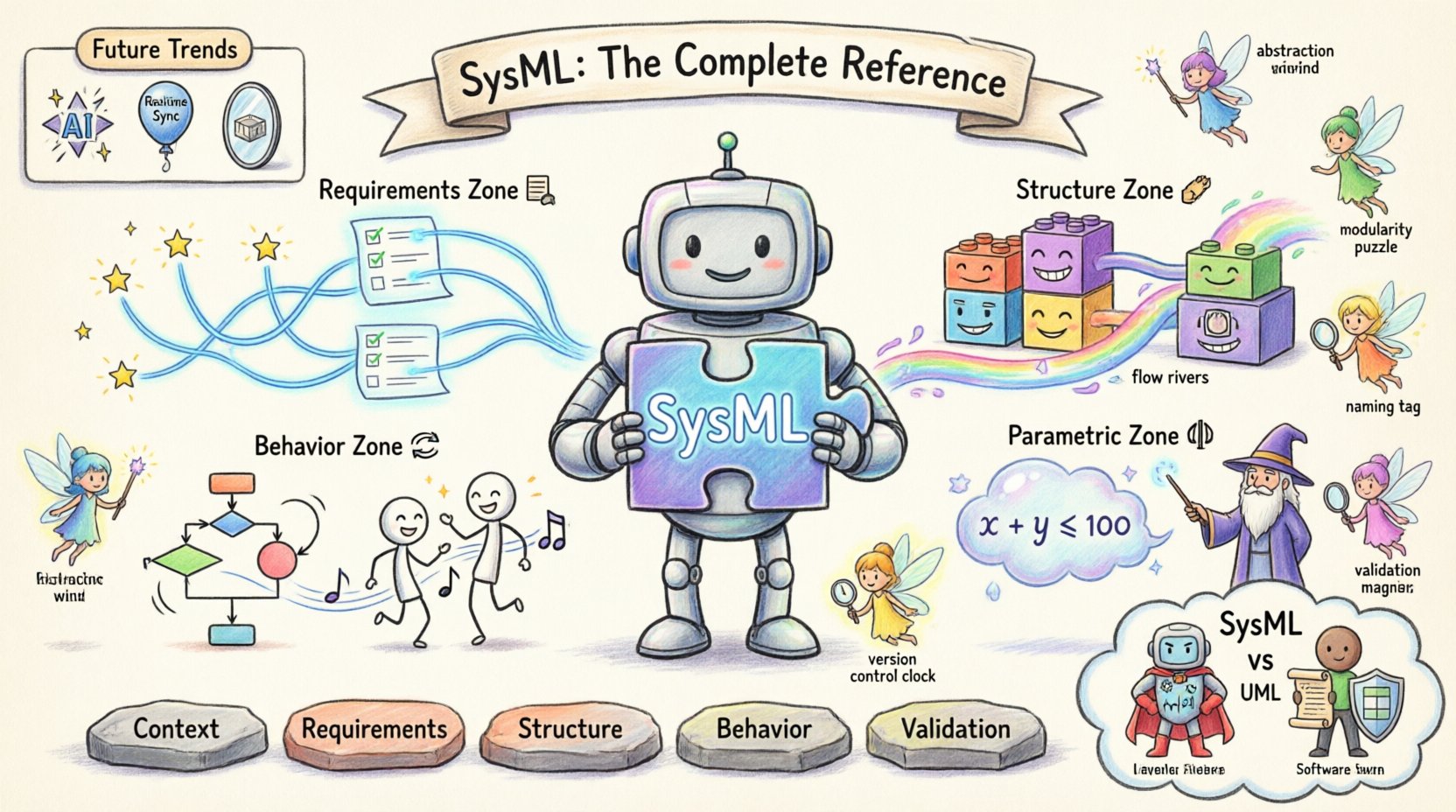
The Four Core Categories of SysML Diagrams 📊
To manage the complexity of large-scale systems, SysML organizes information into four primary diagram categories. Each category serves a specific purpose in the modeling lifecycle. Understanding the distinct role of each diagram type is essential for constructing a coherent system model.
1. Requirements Diagrams 📋
Requirements diagrams capture the needs and constraints that the system must satisfy. They provide the foundation for all other modeling activities. A robust requirements model ensures that every design decision can be traced back to a specific stakeholder need.
- Requirement Element: Represents a specific condition or capability.
- Traceability: Links requirements to other elements, such as blocks or other requirements.
- Refinement: Breaks down high-level requirements into detailed sub-requirements.
- Satisfaction: Indicates that a system element meets a specific requirement.
Traceability is the backbone of the requirements diagram. It allows engineers to verify that no requirement is orphaned. If a requirement is satisfied by a specific block, the link is established explicitly. Conversely, if a block needs to be changed, the impact analysis shows which requirements are affected.
2. Structure Diagrams 🏗️
Structure diagrams describe the physical and logical composition of the system. They define the building blocks of the architecture and how these blocks interact. This is where the “what” of the system is defined.
- Block Definition Diagram (BDD): Shows the hierarchy of blocks and their relationships (composition, aggregation, association).
- Internal Block Diagram (IBD): Details the internal structure of a specific block, showing parts, ports, and connectors.
In an Internal Block Diagram, ports serve as interaction points. A port defines the interface through which a block communicates with other blocks. Flows connect these ports, representing the transfer of data, energy, or material. Understanding the distinction between composition and aggregation is vital. Composition implies a strong ownership where parts cannot exist independently, whereas aggregation implies a weaker relationship.
3. Behavior Diagrams 🔄
Behavior diagrams describe how the system acts over time. They capture the dynamic aspects of the system, including sequences of events, state changes, and activities. These diagrams answer the question: “How does the system operate?”
- Use Case Diagram: Defines the functional requirements from a user perspective.
- Activity Diagram: Models the flow of control and data within a process.
- Sequence Diagram: Shows interactions between objects over time.
- State Machine Diagram: Describes the states of an object and the transitions between them.
Activity diagrams are particularly useful for modeling complex workflows. They support control flows and object flows. State machine diagrams are essential for systems with distinct operational modes, such as a vehicle transitioning from “parked” to “driving”. Sequence diagrams help visualize the timing of messages between components, ensuring that dependencies are met.
4. Parametric Diagrams ⚖️
Parametric diagrams define the mathematical relationships and constraints within the system. They are used for performance analysis and verification. This diagram type allows engineers to apply equations to block properties.
- Constraint Blocks: Contain mathematical equations or logical conditions.
- Variables: Represent parameters like mass, velocity, or temperature.
- Connectors: Link variables to constraint blocks to form equations.
For example, a constraint block might define the relationship between force, mass, and acceleration. By linking these variables to specific block properties, the model can be solved to verify if a design meets performance criteria. This bridges the gap between qualitative modeling and quantitative analysis.
SysML vs UML: Key Differences 🆚
While SysML is derived from UML, it is not a direct replacement for all UML use cases. UML focuses primarily on software systems, whereas SysML addresses broader engineering concerns including hardware, physics, and logistics. The table below outlines the distinctions.
| Feature | UML | SysML |
|---|---|---|
| Primary Focus | Software Design | Systems Engineering |
| Requirements | Limited support | First-class citizen |
| Parametrics | None | Integrated support |
| Structure | Class Diagrams | Blocks & Parts |
| Extensibility | Profiles | Profiles & Extensions |
In UML, classes represent software entities. In SysML, blocks represent physical or logical system components. This shift allows SysML to model hardware interfaces and physical constraints which UML cannot natively handle. The inclusion of a dedicated requirements diagram type is the most significant functional difference, placing system needs at the center of the design process.
Implementing SysML in MBSE Workflows 🚀
Integrating SysML into a Model-Based Systems Engineering (MBSE) workflow requires a structured approach. It is not merely about drawing diagrams; it is about managing information flow across the project lifecycle.
Step 1: Define the System Context
Begin by identifying the system boundaries. What is inside the system, and what is outside? This definition determines the scope of the model. External entities are modeled as blocks that interact with the system boundary.
Step 2: Establish Requirements Hierarchy
Create the top-level requirements. These should be high-level and measurable. As the design evolves, refine these requirements into functional and performance specifications. Ensure that every requirement has a unique identifier for traceability.
Step 3: Develop Structural Architecture
Design the block hierarchy. Decompose the system into subsystems and components. Define the interfaces between these components using ports and flows. Ensure that the structural model aligns with the requirements established in Step 2.
Step 4: Model Behavior and Logic
Once the structure is defined, model the behavior. Determine how the system transitions between states. Map activities to specific blocks. Use sequence diagrams to validate interaction protocols between subsystems.
Step 5: Validate Performance
Apply parametric constraints to verify performance. If the model satisfies the equations, the design is viable. If not, iterate on the structural or behavioral models. This loop ensures that the system meets its engineering goals.
Best Practices for Model Management 🛠️
Maintaining a large SysML model requires discipline. Without governance, models can become cluttered and difficult to navigate. Adopting best practices ensures the model remains a valuable asset throughout the project.
- Abstraction Levels: Do not model every detail at once. Use high-level views for stakeholders and detailed views for engineers.
- Modularity: Organize diagrams into logical packages. Keep related diagrams together to reduce navigation time.
- Naming Conventions: Use consistent naming for blocks, ports, and flows. Ambiguity in names leads to confusion in interpretation.
- Version Control: Treat models like code. Track changes and manage versions to revert to previous states if necessary.
- Validation: Regularly check the model for consistency. Ensure that all requirements are linked and all flows are connected.
Consistency is key. A model that contradicts itself is more harmful than no model at all. Automated validation rules can help enforce these standards, checking for orphaned requirements or unconnected ports.
Challenges in SysML Adoption ⚠️
While the benefits are clear, organizations often face hurdles when transitioning to SysML. Recognizing these challenges early allows for better planning and mitigation strategies.
- Learning Curve: Engineers accustomed to text-based requirements may struggle with visual modeling. Training programs are essential.
- Tool Integration: Connecting the modeling environment with simulation or code generation tools can be complex.
- Model Bloat: Without strict governance, models can grow too large. Limit the scope of each diagram to maintain clarity.
- Stakeholder Buy-in: Management must understand the value of MBSE to justify the initial investment in training and tools.
Advanced Modeling Concepts 🔬
For complex systems, standard modeling techniques may not suffice. Advanced concepts allow for deeper analysis and flexibility.
Time and Event Modeling
Timing constraints are critical in real-time systems. SysML allows the definition of time properties on flows and blocks. This enables the analysis of latency, jitter, and throughput within the model.
Multi-Domain Modeling
Systems often span multiple engineering domains, such as electrical, mechanical, and software. SysML supports the integration of these domains within a single model. This holistic view prevents silos where mechanical engineers and software engineers work in isolation.
Simulation Integration
While SysML defines the structure and behavior, simulation tools perform the calculation. The model serves as the input for simulation environments. Results from simulation can feed back into the model to update parameters or validate assumptions.
Future Trends in Systems Modeling 🌐
The field of systems engineering continues to evolve. As systems become more interconnected, the demand for robust modeling languages grows. Future developments in SysML may focus on increased automation and AI integration.
- AI-Assisted Modeling: Algorithms could suggest model structures based on requirement patterns.
- Cloud Collaboration: Real-time collaboration on models across distributed teams.
- Digital Twins: Direct linkage between SysML models and live physical systems for continuous monitoring.
These trends point toward a future where models are not static documents but living representations of the system throughout its entire lifecycle. The language itself will adapt to support these new capabilities while maintaining backward compatibility.
Summary of Key Takeaways 📝
SysML provides a rigorous framework for systems engineering. By unifying requirements, structure, behavior, and constraints, it offers a comprehensive view of system design. The language supports the transition to MBSE, reducing reliance on error-prone text documents. Successful implementation requires adherence to best practices, clear governance, and continuous training. For organizations aiming to improve quality and reduce risk, SysML is a foundational tool.
Understanding the distinctions between diagram types is crucial. Requirements drive the design, structure defines the components, behavior dictates the logic, and parametrics validate the performance. Together, they form a cohesive model that guides the engineering process from concept to operation.