


In the landscape of Model-Based Systems Engineering (MBSE), clarity is paramount. Engineers and architects constantly navigate the complex terrain of system design, seeking ways to represent structure and intent with precision. Two of the most critical tools in the Systems Modeling Language (SysML) toolkit are the Requirements Diagram and the Block Definition Diagram. While both are fundamental to the standard, they serve distinct purposes and operate on different layers of abstraction.
Choosing the right diagram at the right time prevents model bloat and ensures that stakeholders can interpret the system definition without confusion. This guide provides a deep dive into the mechanics, applications, and strategic differences between these two diagram types. We will explore their structural elements, relationship types, and specific scenarios where one outperforms the other. Whether you are defining a high-level architecture or tracing a specific safety requirement, understanding this distinction is vital for robust system definition.
Understanding SysML Fundamentals 🏗️
SysML is a general-purpose modeling language designed to specify, analyze, design, and verify complex systems. It extends the Unified Modeling Language (UML) to address the specific needs of systems engineering. A core tenet of SysML is the separation of concerns. Different diagrams focus on different aspects of the system to keep models manageable.
When building a model, you must decide how to represent the system. Are you defining what the system must do, or are you defining how the system is built? This fundamental question often dictates the choice between a Requirements Diagram and a Block Definition Diagram.
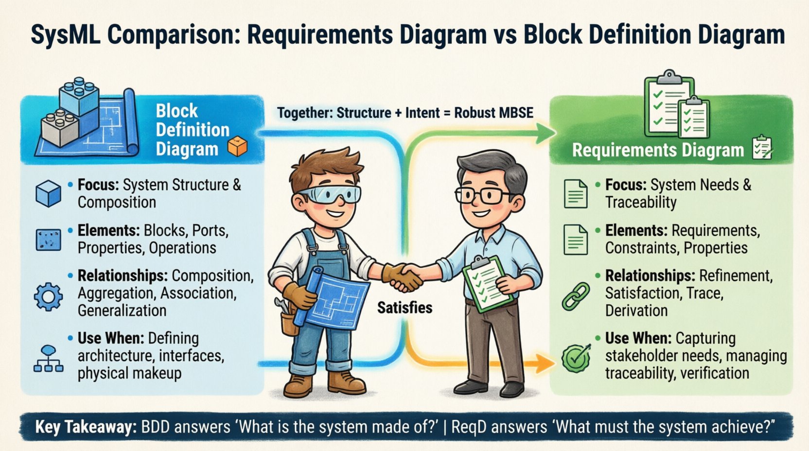
- Requirements Diagram: Focuses on the needs, constraints, and conditions the system must satisfy. It is the primary vehicle for traceability and validation.
- Block Definition Diagram: Focuses on the composition, structure, and internal organization of the system. It defines the physical or logical parts that make up the whole.
Confusion often arises because both diagrams deal with “items.” However, in SysML, an item in a requirements context is a logical need, whereas an item in a block context is a structural component. Keeping this distinction clear is the first step toward effective modeling.
The Block Definition Diagram (BDD) 🧱
The Block Definition Diagram is the cornerstone of system architecture in SysML. It provides a high-level view of the system’s structure. Think of it as the blueprint for the system’s skeleton. It defines the blocks, their properties, and the relationships between them.
Core Elements of the BDD
Several specific elements make up the BDD. Understanding these is essential for accurate modeling.
- Blocks: The fundamental unit of structure. A block represents a physical or logical component. It can be a single piece of hardware, a software module, a subsystem, or even an abstract concept.
- Properties: These define the characteristics of a block. A property is a part of a block. For example, an engine is a block, and its fuel tank is a property of that engine.
- Ports: Ports define the interfaces where a block interacts with its environment or other blocks. They specify the type of information or energy that flows in or out.
- Operations: Blocks can define behaviors they perform. Operations are the functions or methods associated with a block.
- Constraints: While BDDs primarily handle structure, constraints can be applied to blocks to define mathematical limits or logical conditions on properties.
Relationships in BDD
The power of the BDD lies in how blocks relate to one another. These relationships define the composition of the system.
- Association: A generic link between blocks. It indicates that instances of one block are connected to instances of another. It does not imply ownership.
- Aggregation: A weaker form of composition. It implies a “whole-part” relationship where the parts can exist independently of the whole. For example, a library has books, but the books can exist without the library.
- Composition: A strong form of aggregation. It implies that the parts cannot exist without the whole. If the whole is destroyed, the parts are destroyed. This is critical for defining system hierarchy.
- Generalization: Defines inheritance. A specific block is a specialized version of a more general block. This helps in reusing structural definitions.
When to Use BDD
You should deploy a Block Definition Diagram when you need to define the architecture. It is the go-to diagram for:
- Establishing the system hierarchy and decomposition.
- Defining interfaces between subsystems.
- Specifying the physical or logical makeup of the system.
- Visualizing the flow of data or energy through structural connections.
- Documenting the internal structure of a specific subsystem.
For instance, if you are designing a spacecraft, the BDD defines the main bus, the power distribution unit, the thermal control system, and how they are physically connected. It answers the question: “What is the system made of?”
The Requirements Diagram (ReqD) 📋
The Requirements Diagram is the primary tool for managing the lifecycle of system needs. It allows you to organize requirements, define their hierarchy, and link them to other elements in the model. Unlike the BDD, which focuses on physical structure, the ReqD focuses on intent and obligation.
Core Elements of the ReqD
The ReqD has a specific set of elements designed to manage logic and traceability.
- Requirements: A statement of a need or condition to be met. Requirements are categorized by type (e.g., Functional, Performance, Interface).
- Requirement Diagrams: The container that holds the requirements and their relationships. A single system model can contain multiple requirement diagrams for different domains.
- Requirement Properties: Attributes like ID, Priority, Status, and Verification Method can be attached to requirements.
- Constraints: Mathematical or logical expressions that limit the behavior or state of the system.
Relationships in ReqD
Traceability is the superpower of the Requirements Diagram. SysML defines four specific relationship types for requirements:
- Refinement: Links a high-level requirement to a more detailed sub-requirement. It shows how a need is broken down into manageable pieces.
- Trace: Links two requirements that are logically related but not necessarily hierarchical. For example, a requirement from a customer might trace to a derived requirement from a subsystem.
- Satisfaction: Links a requirement to a design element (like a block or activity) that fulfills it. This is crucial for verification.
- Derivation: Links a requirement to another requirement from which it was logically derived. This often happens during the decomposition process.
When to Use ReqD
The Requirements Diagram is essential when you need to manage the “why” and the “what” of the system. Use it for:
- Capturing stakeholder needs and constraints.
- Building a traceability matrix between needs and design.
- Ensuring every requirement is satisfied by a design element.
- Managing the impact of requirement changes across the model.
- Verifying that no orphaned requirements exist in the system.
Using a ReqD ensures that the system is built to meet the mission. It answers the question: “What must the system achieve?”
Key Structural Differences 🆚
To solidify the distinction, let us look at a side-by-side comparison of how these diagrams handle data, relationships, and scope.
| Feature | Block Definition Diagram (BDD) | Requirements Diagram (ReqD) |
|---|---|---|
| Primary Focus | System Structure & Composition | System Needs & Traceability |
| Core Elements | Blocks, Ports, Properties, Operations | Requirements, Constraints, Relationships |
| Key Relationships | Composition, Aggregation, Association | Refinement, Satisfaction, Trace, Derivation |
| Scope | Physical/Logical Architecture | Functional/Performance Intent |
| Verification Link | Satisfied by (via Satisfaction Relationship) | Satisfies (via Satisfaction Relationship) |
| Change Impact | Structural changes affect interfaces | Requirement changes affect validation |
This table highlights that while they interact, they do not overlap in function. The BDD describes the container, while the ReqD describes the content of the mission.
When to Choose BDD Over ReqD 🏗️
There are specific phases of the systems engineering lifecycle where the Block Definition Diagram is the superior choice. Relying on a ReqD for structural definition leads to confusion.
1. Defining the System Hierarchy
When you are at the top level of a project, you need to break the system down into manageable subsystems. The BDD allows you to define a top-level block and compose it with lower-level blocks. This creates a clear decomposition tree.
- Use Composition to show ownership.
- Use Generalization to show reusable subsystems.
- Use Properties to define the inventory of the system.
2. Specifying Interfaces
Interfaces are the boundaries where systems meet. In SysML, interfaces are often modeled using ports and flows on a BDD. If you need to define the voltage, data protocol, or mechanical mounting points, the BDD is the correct canvas.
- Define standard interfaces to ensure compatibility.
- Visualize the flow of signals between blocks.
- Ensure that the physical connectivity matches the logical connectivity.
3. Modeling Physical Constraints
If a system has physical limitations, such as weight, volume, or power consumption, these are often modeled as properties of blocks in the BDD. While you can use constraints in ReqD, structural constraints are best placed on the blocks themselves.
4. Architecture Reviews
During architecture reviews, stakeholders need to see the structure. They ask about the components and how they fit together. A BDD provides the visual evidence of the architectural decisions made. It is the map of the system’s physical reality.
When to Choose ReqD Over BDD 🎯
Conversely, there are scenarios where the BDD is insufficient. If the focus is on compliance, validation, or mission success, the Requirements Diagram takes precedence.
1. Capturing Stakeholder Needs
The first step in any project is understanding what the customer wants. This is a logical exercise, not a structural one. You cannot draw a block for a “customer satisfaction level.” You must use a Requirement to capture this intent.
- Record all functional and non-functional requirements.
- Assign priorities and verification methods immediately.
- Ensure no requirement is lost during the design process.
2. Managing Traceability
Traceability is the ability to follow a requirement from its origin to its implementation. The ReqD is the only diagram designed to show this lineage clearly. It links a stakeholder need to a derived requirement, and then to a design block.
- Link high-level needs to low-level specs.
- Link requirements to the blocks that satisfy them.
- Link requirements to tests that verify them.
3. Ensuring Completeness
One of the biggest risks in systems engineering is having a design without a requirement, or a requirement without a design. The ReqD helps you audit this. You can check if every requirement has a “Satisfies” relationship pointing to a block or activity.
4. Handling Change Management
When a requirement changes, you need to know the impact. The ReqD allows you to trace the requirement to all dependent elements. If a performance requirement changes, you can see which blocks rely on that performance metric.
Integrating Structure and Requirements 🔗
The true power of SysML emerges when these two diagrams are used in tandem. They are not mutually exclusive; they are complementary. A robust model connects the BDD and the ReqD through specific relationships.
1. Allocation
Allocation is the process of assigning requirements to structural elements. In the model, this is often achieved by creating a “Satisfies” relationship from the Requirement (in ReqD) to the Block (in BDD). This validates that the structure exists to meet the need.
- Ensure every requirement is allocated.
- Ensure every block has a purpose.
- Use allocation to verify coverage.
2. Refinement of Structure
As you decompose a block in the BDD, you should also decompose the requirements in the ReqD. This keeps the structure aligned with the intent. If you split a block into two, you must ensure the requirements are also split or allocated correctly to the new parts.
3. Parameter Propagation
Properties on blocks can be linked to parameters on requirements. This allows you to drive design values from requirement constraints. For example, a weight limit in the ReqD can propagate to the mass property of a block in the BDD.
Common Modeling Pitfalls ⚠️
Even experienced modelers can stumble when distinguishing between these diagrams. Recognizing common mistakes helps maintain model integrity.
1. Mixing Logic and Structure
A common error is placing requirements inside a Block Definition Diagram. Requirements are logical entities, not structural parts. Placing them in a BDD conflates the “what” with the “how.” Keep them in the ReqD.
- Do not treat a requirement as a block.
- Do not place a requirement inside a composition relationship.
- Keep structural hierarchy separate from requirement hierarchy.
2. Over-Complicating the ReqD
Because the ReqD is about logic, it can easily become a tangled web of lines. Avoid creating a single, massive requirement diagram for an entire system. Instead, use multiple diagrams for different domains or subsystems.
- Group related requirements together.
- Use refinement to create sub-diagrams.
- Focus on traceability, not just listing text.
3. Ignoring the Satisfaction Relationship
Many models list requirements and blocks but fail to link them. Without the “Satisfies” relationship, there is no proof that the system meets the needs. This creates a gap between design and verification.
- Always link requirements to blocks.
- Ensure the link is bidirectional where possible.
- Audit the links during reviews.
4. Using BDD for Functional Flow
While BDDs show connections, they are not meant to show sequence or flow of control. For that, use an Activity Diagram or Sequence Diagram. Using a BDD to show how the system operates over time creates confusion about static vs. dynamic behavior.
Best Practices for Effective Modeling ✅
To ensure your SysML models are robust and useful, follow these guidelines for managing Requirements and Blocks.
- Maintain Consistency: If you change a block name in the BDD, ensure the requirement that references it is updated. Consistency is key for automated analysis.
- Naming Conventions: Adopt a strict naming convention. For blocks, use physical names (e.g., “Hydraulic Pump”). For requirements, use logical names (e.g., “Maintain Pressure > 100 PSI”).
- Layering: Do not mix high-level and low-level details on the same diagram. Create a top-level BDD for architecture and detailed BDDs for subsystems. Do the same for requirements.
- Use Profiles: If your organization has specific standards, define them as profiles. This ensures that blocks and requirements adhere to company-wide standards without cluttering the core model.
- Regular Audits: Periodically run traceability checks. Ensure that the ratio of satisfied requirements is high and that no blocks are orphaned.
Summary of Strategic Choices 📝
Selecting between a Requirements Diagram and a Block Definition Diagram depends on the specific engineering question you are answering. The BDD answers questions about composition, interfaces, and physical structure. It is the map of the system’s body.
The ReqD answers questions about intent, compliance, and validation. It is the map of the system’s mission. By understanding the unique strengths of each, you can build models that are both structurally sound and mission-critical.
Effective systems engineering requires a balance. You need the structure to hold the system together, and you need the requirements to ensure the system works. Neither is sufficient on its own. When used correctly, the BDD and ReqD work in harmony to deliver complex systems on time and within specification.
As you continue your modeling journey, remember to keep the concerns separated. Use the BDD for the hardware and software architecture. Use the ReqD for the logic and needs. This separation of concerns will reduce complexity and increase the reliability of your models.
By adhering to these practices, you ensure that your SysML models remain clear, maintainable, and valuable assets for your engineering teams. The choice is clear: structure for the build, requirements for the purpose.