


Systems engineering deals with complexity. It involves coordinating hardware, software, people, processes, and data across the lifecycle of a product. When systems grow in size and sophistication, traditional document-based methods struggle to maintain clarity and traceability. This is where the Systems Modeling Language (SysML) enters the picture. SysML is an open, general-purpose modeling language designed to support the systems engineering process. It provides a standardized way to describe, analyze, verify, and validate complex systems.
This guide offers a comprehensive breakdown of SysML. It covers the core syntax, the specific diagram types, the relationship to Model-Based Systems Engineering (MBSE), and practical considerations for adoption. We will move past the jargon and focus on how this standard functions in a technical environment.
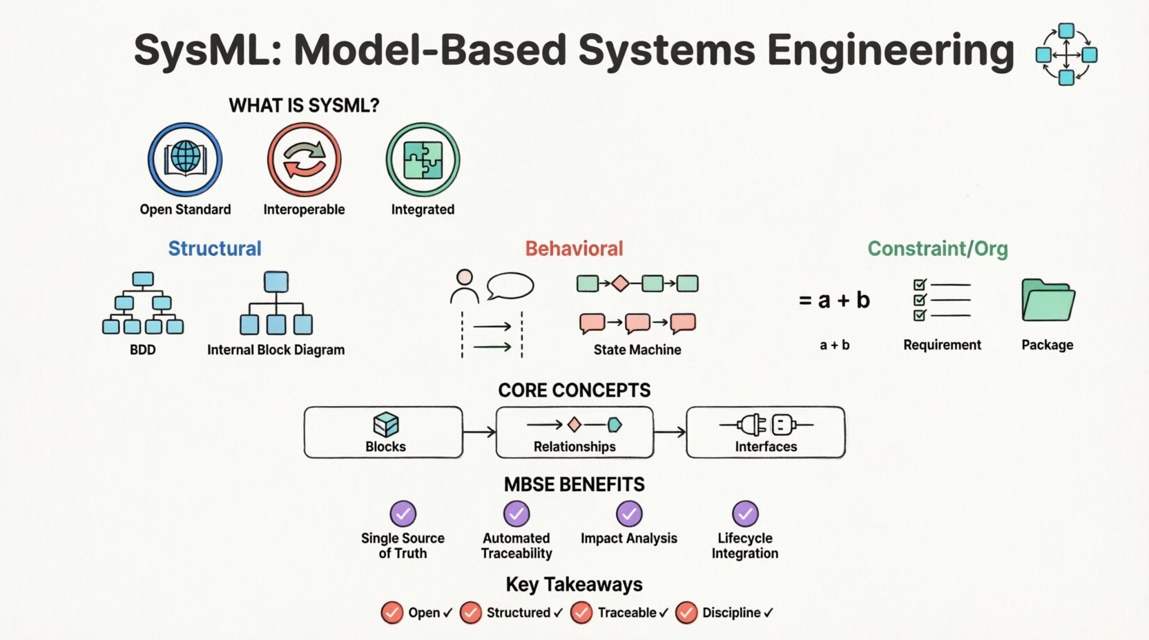
What Exactly is SysML? 🤔
SysML is a general-purpose modeling language. It was developed to extend the Unified Modeling Language (UML) specifically for systems engineering. While UML was originally designed for software, its flexibility allowed for adaptation. SysML is a profile of UML 2, meaning it reuses UML constructs but adds new ones or restricts existing ones to fit system engineering needs.
The primary goal of SysML is to facilitate Model-Based Systems Engineering (MBSE). In a document-centric approach, requirements, designs, and verification plans exist in separate files. Changes are difficult to track across these silos. SysML introduces a central model repository. This repository holds the definitions of system elements, their behaviors, and their requirements in a unified structure.
Key characteristics of the language include:
- Open Standard: It is maintained by the Object Management Group (OMG). There are no proprietary licenses required to use the language syntax.
- Interoperable: Models created with one tool should theoretically be readable by another, provided both adhere to the standard.
- Integrated: It covers structure, behavior, requirements, and parameters within a single modeling environment.
SysML vs. UML: Understanding the Distinction 📊
Many practitioners confuse SysML with UML. While they share a common lineage, their purposes diverge. UML focuses heavily on software architecture, object interactions, and class structures. SysML shifts the focus to physical systems, performance constraints, and stakeholder requirements.
Here is a breakdown of the differences:
- Requirements: SysML has a dedicated diagram type for requirements management (Requirement Diagram). UML handles requirements only through notes or stereotypes.
- Physical Structure: SysML explicitly models physical connections and interfaces (Internal Block Diagram). UML focuses on logical associations.
- Performance: SysML includes Parametric Diagrams for defining mathematical constraints and performance equations. UML does not have native support for this.
- Blocks: In SysML, the Block represents a system or component that has mass, volume, and physical properties. In UML, a Class represents data and methods.
Understanding this distinction is vital. Using UML for hardware systems engineering often leads to models that lack the necessary rigor regarding physical constraints and external interfaces.
The 9 Diagram Types of SysML 📐
SysML is structured around nine distinct diagram types. These diagrams are not just drawings; they are views into the same underlying data model. Each diagram serves a specific purpose within the engineering lifecycle. Below is a summary table followed by detailed explanations.
| Diagram Type | Category | Primary Purpose |
|---|---|---|
| Block Definition Diagram (BDD) | Structural | Define system hierarchy and composition |
| Internal Block Diagram (IBD) | Structural | Define internal structure and interfaces |
| Use Case Diagram | Behavioral | Define functional requirements and actors |
| Activity Diagram | Behavioral | Model workflows and logic |
| Sequence Diagram | Behavioral | Model interactions over time |
| State Machine Diagram | Behavioral | Model state transitions and control flow |
| Parametric Diagram | Constraint | Define mathematical performance constraints |
| Requirement Diagram | Requirements | Manage and trace requirements |
| Package Diagram | Organization | Organize model elements |
Structural Diagrams: The Skeleton of the System
Structural diagrams define the components of the system and how they relate to one another. They answer the question: What is it made of?
1. Block Definition Diagram (BDD)
The BDD is the most fundamental diagram in SysML. It represents the static structure of the system. It defines Blocks. A block is the most general representation of a thing. It can be a physical part, a subsystem, or a logical function.
- Composition: BDDs show how blocks are composed of other blocks (aggregation, association).
- Inheritance: It defines how blocks inherit properties from other blocks (generalization).
- Interfaces: It specifies provided and required interfaces that blocks expose to the outside world.
2. Internal Block Diagram (IBD)
While the BDD shows the external view, the IBD shows the internal view. It details how the parts inside a block are connected.
- Parts: It lists the instances of blocks contained within the parent block.
- Connectors: It shows how data, energy, or material flows between parts.
- Ports: It defines the interaction points where external connections are made.
Behavioral Diagrams: The Logic of the System
Behavioral diagrams describe how the system behaves over time. They answer the question: What does it do?
3. Use Case Diagram
This diagram captures functional requirements from the perspective of external actors (users, other systems, or environments).
- Actors: Represent entities interacting with the system.
- Use Cases: Represent specific functional goals.
- Relationships: Define how actors trigger use cases.
4. Activity Diagram
Activity diagrams model the flow of control or data. They are similar to flowcharts but include features for concurrency and object flow.
- Nodes: Represent steps in a process (action nodes, decision nodes).
- Forks: Allow parallel execution of activities.
- Junctions: Allow merging of parallel flows back into a single flow.
5. Sequence Diagram
Sequence diagrams focus on the time-ordered exchange of messages between objects or blocks.
- Lifelines: Represent the participants in the interaction.
- Messages: Show the flow of information between lifelines.
- Focus of Control: Indicates when a participant is actively executing.
6. State Machine Diagram
This diagram models the life cycle of a single block. It is essential for systems with complex state-dependent behaviors.
- States: Represent conditions during the life of an object.
- Transitions: Define how the system moves from one state to another based on events.
- Events: The triggers that cause a transition.
Constraint and Organization Diagrams
These diagrams support the structural and behavioral views with mathematical rigor and organization.
7. Parametric Diagram
This is a unique feature of SysML. It allows for the definition of mathematical constraints on system properties.
- Constraints: Blocks that represent equations or rules.
- Constraint Blocks: Define reusable sets of equations.
- Binding: Links constraint blocks to system properties.
8. Requirement Diagram
This diagram manages the requirements throughout the lifecycle. It ensures every design element can be traced back to a stakeholder need.
- Requirement Elements: Atomic requirements.
- Traceability: Relationships like Satisfy, Verify, Refine, and Derive.
9. Package Diagram
Complex models become unmanageable without organization. Package diagrams organize elements into namespaces.
- Namespaces: Prevent naming conflicts.
- Imports: Allow elements from one package to be used in another.
Core Concepts and Semantics 🔧
Understanding the diagrams is only half the battle. To use SysML effectively, one must understand the semantics of the core elements.
Blocks and Properties
A Block is the fundamental unit of definition. It is a generic classifier that can represent anything from a physical component to a logical function. Blocks have properties.
- Part Properties: Instances of other blocks contained within the main block.
- Reference Properties: References to external blocks (not owned by the parent).
- Value Properties: Simple data attributes (integers, strings, booleans).
Relationships
Connections between blocks are not arbitrary. They have specific meanings:
- Association: A structural link between two blocks.
- Aggregation: A whole-part relationship where the parts can exist independently of the whole.
- Composition: A strong whole-part relationship where parts cannot exist without the whole.
- Dependency: A usage relationship where one element depends on another.
Interfaces
Interfaces define the behavior and structure exposed by a block without revealing its internal implementation. This separation of interface and implementation is critical for modular design.
- Provided Interface: The services the block offers to others.
- Required Interface: The services the block needs from others.
MBSE: The Context for SysML 🌍
SysML is the language, but MBSE is the methodology. MBSE involves using models as the primary source of information throughout the system lifecycle. SysML is the syntax that makes this possible.
Document-Based vs. Model-Based
In a document-based environment, requirements are in a Word file, design is in CAD, and verification is in Excel. These documents drift apart. A change in requirements might not be reflected in the design document.
In an MBSE environment using SysML:
- Single Source of Truth: The model is the reference.
- Automated Traceability: Links between requirements and design are explicit and maintained by the tool.
- Impact Analysis: Changing a block definition automatically updates all diagrams referencing that block.
The Lifecycle Integration
SysML supports the entire lifecycle:
- Conceptual Design: Use Case and Requirement diagrams.
- Preliminary Design: Block Definition and Activity diagrams.
- Detail Design: Internal Block and State Machine diagrams.
- Verification: Parametric and Requirement diagrams ensure constraints are met.
Implementation Challenges and Best Practices 🚧
Adopting this standard is not without hurdles. Teams often underestimate the cognitive load required to learn the language.
Common Pitfalls
- Over-Modeling: Creating diagrams for every single detail before understanding the high-level architecture. Start with the BDD and Requirements.
- Diagram Clutter: Trying to put too much information on one diagram. Break complex systems into packages.
- Ignoring Semantics: Using the visual tools without understanding the underlying logic. A connector in SysML means something specific; do not treat it as a decorative line.
Best Practices for Adoption
- Define a Standard First: Establish naming conventions, folder structures, and diagram templates before starting work.
- Train the Team: Ensure all engineers understand the difference between a Part and a Property, or a State and an Activity.
- Iterative Modeling: Start with the requirements and work outward to the design. Do not reverse-engineer the model from a CAD file.
- Leverage Automation: Use the model to generate documentation or reports, rather than drawing manually.
Future Outlook and Standards 📈
The systems engineering landscape is evolving. The adoption of MBSE is increasing in aerospace, automotive, and defense sectors. The standard itself continues to evolve.
Standardization
As the OMG maintains the standard, interoperability improves. The goal is to allow models to be exchanged between different organizations and tool vendors without data loss. This is critical for supply chain management where multiple vendors contribute to a single system.
Integration with Digital Twins
The concept of the Digital Twin relies heavily on accurate system models. SysML provides the structural and behavioral foundation for these twins. As simulations become more complex, the ability to define constraints mathematically (Parametric Diagrams) becomes increasingly valuable.
Summary of Key Takeaways ✅
SysML is a powerful tool for managing complexity. It is not merely a drawing tool; it is a language for defining system architecture. By separating structure, behavior, requirements, and constraints, it provides a holistic view of engineering systems.
Key points to remember:
- It is Open: No licensing fees for the language itself.
- It is Structured: The 9 diagram types cover all aspects of systems engineering.
- It Enables Traceability: Requirements are linked directly to design elements.
- It Requires Discipline: Consistent modeling practices are necessary to maintain model integrity.
For organizations looking to improve system reliability and reduce lifecycle costs, moving toward a model-based approach using this standard is a logical step. The learning curve exists, but the long-term benefits in clarity and communication outweigh the initial investment.