


In the landscape of Model-Based Systems Engineering (MBSE), the integrity of a system architecture relies heavily on how well abstract concepts translate into tangible reality. SysML, the Systems Modeling Language, provides the syntax for this translation. However, syntax alone does not guarantee functionality. The true value emerges when we successfully map physical assets to logical blocks. This process, known as component breakdown and allocation, ensures that every requirement has a home, every interface has a connection, and every physical constraint is accounted for within the digital twin.
Understanding this mapping is critical for engineers who need to bridge the gap between design intent and manufacturing reality. Without precise alignment, discrepancies arise during integration, leading to cost overruns and schedule delays. This guide explores the methodologies, technical structures, and best practices required to achieve high-fidelity mapping within a SysML environment.
🧠 Core Concepts: Logical vs. Physical Perspectives
To map effectively, one must first distinguish between the logical representation of a system and its physical implementation. In SysML modeling, these distinctions are fundamental to the Block Definition Diagram (BDD) and Internal Block Diagram (IBD) structures.
The Logical Block
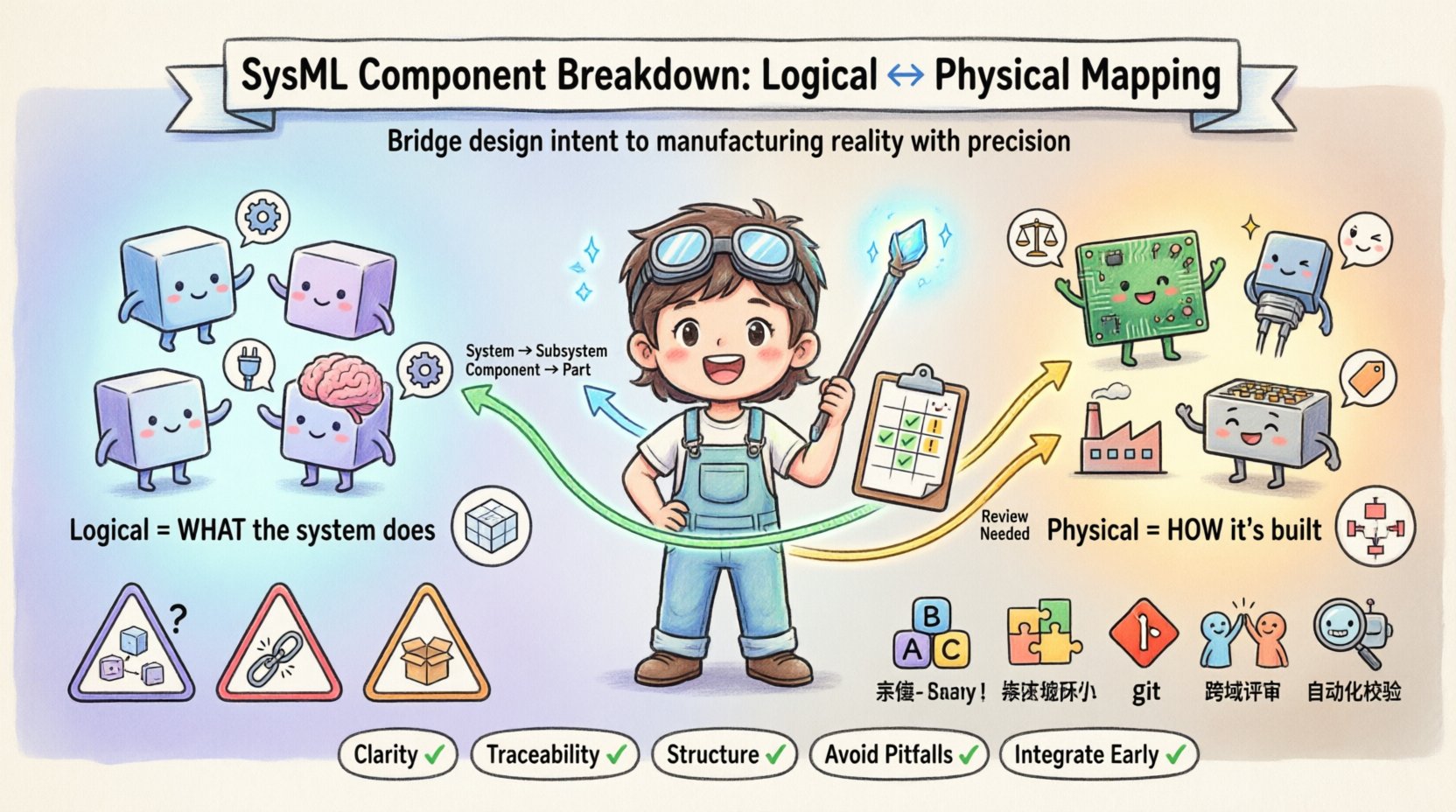
A logical block represents the functional intent of a system component. It defines what the system must do, independent of how it is built. Logical blocks focus on:
- Functionality: The specific operations or behaviors required.
- Interfaces: The inputs and outputs necessary for interaction with other blocks.
- Logic: The decision-making processes or data transformations.
Logical blocks are often abstract. For instance, a “Control Unit” in a logical model might represent the decision-making logic required to manage power distribution, regardless of whether that logic resides in a microcontroller, a PLC, or a software stack running on a server.
The Physical Block
A physical block represents the tangible implementation of a logical concept. It defines the hardware, software, or material components that realize the function. Physical blocks focus on:
- Material Properties: Weight, dimensions, thermal characteristics, and conductivity.
- Implementation Constraints: Manufacturing tolerances, mounting requirements, and environmental ratings.
- Vendor Specifics: Part numbers, suppliers, and off-the-shelf components.
When mapping logical blocks to physical assets, the goal is to ensure that the physical constraints do not negate the logical requirements. This requires a structured breakdown process.
🗺️ The Component Breakdown Strategy
Component breakdown is the process of decomposing a high-level system into smaller, manageable subsystems and components. In the context of mapping physical assets, this breakdown must align with the physical reality of the product. A purely functional decomposition may result in physical components that are difficult to source or manufacture.
1. Defining the Decomposition Levels
Effective breakdown requires establishing clear levels of granularity. Typically, a system is decomposed into:
- System Level: The overall product or vehicle.
- Subsystem Level: Major functional groups (e.g., Power, Propulsion, Guidance).
- Component Level: Individual units (e.g., Battery Pack, Motor Controller).
- Part Level: Raw materials or sub-assemblies (e.g., Capacitor, Gear).
Each level must be traceable to the next. A logical block at the Subsystem Level must map to one or more physical blocks at the Component Level. This hierarchy ensures that requirements flow down correctly.
2. Establishing Allocation Matrices
Allocation is the assignment of requirements and functions to system elements. A matrix approach helps visualize these relationships. The following table outlines the typical characteristics used to differentiate logical and physical allocations.
| Attribute | Logical Block | Physical Block |
|---|---|---|
| Primary Focus | Function & Behavior | Form, Fit, & Function |
| Dependency | System Architecture | Supply Chain & Manufacturing |
| Change Trigger | Requirement Change | Design Iteration or Vendor Change |
| Traceability | Requirement to Block | Block to Part Number |
| Validation | Simulation & Analysis | Testing & Inspection |
Using such a matrix during the modeling process helps maintain clarity. It ensures that engineers know which block type they are defining and what attributes are relevant at that stage.
🔗 Mapping Methodology: Connecting the Dots
Mapping logical blocks to physical assets is not merely a naming convention; it is a structural relationship defined within the SysML model. This involves specific diagram types and relationship types to ensure traceability.
1. Utilizing Block Definition Diagrams (BDD)
The BDD is the primary tool for defining the structure of the system. Here, logical blocks are defined as top-level entities. To introduce physical mapping, engineers often define specialized physical blocks that inherit or specialize the logical blocks. This creates a clear lineage.
- Specialization: Define a physical block that is a subtype of a logical block. This implies the physical block satisfies the interface of the logical block.
- Composition: Use composition relationships to show that a logical system is composed of physical subsystems.
2. Internal Block Diagrams (IBD) for Interface Management
While BDDs define structure, IBDs define interactions. Mapping physical assets requires defining how they connect physically. This is done using parts and connectors.
- Parts: Represent instances of blocks within a composite. In a physical mapping, a part might represent a specific physical sensor installed in a chassis.
- Ports: Define the points of interaction. Logical ports define the signal flow, while physical ports might define the connector type (e.g., HDMI, M12).
- Connectors: Define the physical link between ports. This is where cabling, wiring harnesses, and mechanical fasteners are modeled.
By defining these connections explicitly, the model captures not just the logic, but the physical reality of signal propagation and mechanical load.
🔍 Traceability and Verification
The ultimate measure of a successful component breakdown is traceability. If a requirement is written, it must be possible to trace it to a logical block, and subsequently to a physical asset that satisfies it.
1. Requirement Allocation
Requirements should not sit in a vacuum. They must be allocated to specific blocks. The flow of allocation typically looks like this:
- System Requirement: “The system shall operate in temperatures between -40°C and 85°C.”
- Allocated to: Logical Thermal Management Block.
- Allocated to: Physical Cooling Fan Block.
- Allocated to: Physical Heat Sink Component.
This chain ensures that if the physical heat sink is changed, the impact on the system requirement can be assessed immediately.
2. Verification Links
Verification is the process of proving that a requirement is met. In SysML, verification is often linked to the physical block that performs the test. For example:
- Analysis: Logical blocks are verified through simulation (e.g., thermal simulation).
- Inspection: Physical blocks are verified through dimensional inspection.
- Test: Physical assets are verified through environmental chamber testing.
By linking the verification action to the physical block, the model becomes a living document of the test plan. This reduces the risk of testing the wrong components or missing critical validation steps.
⚠️ Common Pitfalls in Mapping
Even with a structured approach, errors can occur during the breakdown and mapping process. Recognizing these pitfalls early can save significant time during later engineering phases.
1. Granularity Mismatch
A common issue is the mismatch between the logical granularity and the physical granularity. A logical block might be too large, encompassing multiple physical components, or too small, splitting a single physical component across multiple logical definitions. This creates confusion during manufacturing and maintenance.
- Solution: Align the decomposition levels with the Bill of Materials (BOM) structure. Ensure that one physical part number generally corresponds to one logical block definition.
2. Interface Drift
As the design evolves, logical interfaces may change, but physical connectors might not. If the logical model is updated without updating the physical mapping, the system may become unbuildable. For example, changing a signal protocol logically without updating the physical wire gauge or connector type.
- Solution: Enforce strict interface management. Any change to a logical port must trigger a review of the physical connector requirements.
3. Missing Physical Constraints
Logical blocks often ignore constraints like weight, volume, or power consumption until late in the design. This leads to situations where the logical design is perfect, but the physical implementation is impossible.
- Solution: Include physical property definitions (mass, volume, power) in the physical block definitions from the start. Use value types to define these constraints explicitly.
🏆 Best Practices for Model Integrity
To maintain a high-quality model that supports precise mapping, adhere to the following best practices. These steps help ensure the model remains a reliable source of truth throughout the product lifecycle.
- Standardized Naming Conventions: Use consistent naming for logical and physical blocks. A logical block named “Power Supply” should map to a physical block named “PS-Unit-001”. Avoid ambiguous terms.
- Modular Definitions: Define physical blocks as reusable modules where possible. This allows for common components to be shared across different subsystems without duplicating definitions.
- Version Control: Treat the model like code. Maintain versions for the logical architecture and the physical implementation. Track changes in mapping relationships over time.
- Cross-Domain Review: Conduct reviews that involve both systems engineers (logical) and hardware engineers (physical). This ensures that the mapping makes sense to both disciplines.
- Automated Checks: Where possible, use scripting or model validation rules to ensure that every logical block has at least one physical allocation. This prevents orphaned requirements.
🚀 Moving Forward: Integration and Lifecycle
The mapping process does not end at the design phase. It extends into manufacturing, operations, and decommissioning. A well-structured SysML model serves as the backbone for the entire lifecycle.
1. Manufacturing Handoff
When the model is ready for production, the physical block definitions feed directly into the manufacturing system. The mapping ensures that the BOM generated from the model matches the assembly instructions. Discrepancies between the model and the shop floor are minimized when the logical-to-physical trace is robust.
2. Maintenance and Support
During the operational phase, the model acts as a reference for troubleshooting. If a physical component fails, technicians can trace the fault back to the logical function it supports. This aids in root cause analysis and spare parts management.
3. Continuous Improvement
Feedback from the field should update the model. If a physical component consistently underperforms, the logical block definition should be updated to reflect the new constraints. This closed-loop process ensures the system evolves correctly.
📝 Summary of Key Takeaways
Mapping physical assets to logical blocks in SysML is a disciplined engineering activity that requires attention to detail and structural rigor. It bridges the gap between abstract requirements and concrete hardware.
- Clarity is Key: Distinguish clearly between logical intent and physical implementation.
- Traceability Matters: Ensure every requirement flows down to a physical asset and back up to a verification test.
- Structure Supports Scale: Use BDDs and IBDs to manage complexity and define relationships.
- Avoid Pitfalls: Watch for granularity mismatches and interface drift.
- Integrate Early: Involve physical constraints in the early logical design phases.
By following these principles, engineering teams can reduce risk, improve communication, and deliver systems that are both functionally sound and physically realizable. The precision gained in the model translates directly to efficiency on the floor.