


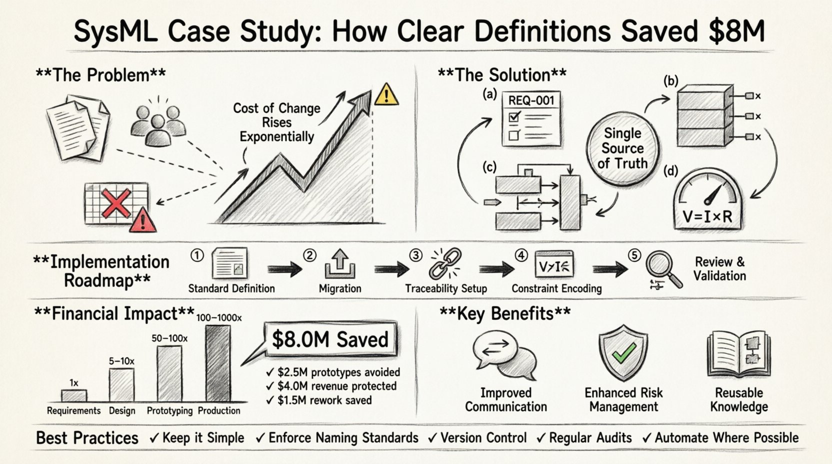
Engineering projects often follow a predictable trajectory. Early phases are defined by exploration and flexibility. As the project matures, the cost of making changes rises exponentially. This phenomenon is well-documented in the cost of change curve. When requirements are vague or models are disconnected from physical reality, late-stage modifications become financially devastating.
In complex systems engineering, Model-Based Systems Engineering (MBSE) has emerged as a critical discipline. Specifically, the Systems Modeling Language (SysML) provides a standardized way to represent system structures, behaviors, and requirements. A recent industry case study highlights how adopting clear SysML definitions prevented catastrophic rework. This article explores the technical details of that transformation, the specific modeling techniques used, and the quantifiable impact on the project budget.
The Challenge: Ambiguity in Late-Stage Development 📉
Consider a large-scale infrastructure project involving multiple subsystems: power distribution, thermal management, and control logic. In the traditional approach, requirements existed in documents, designs existed in CAD files, and verification data existed in spreadsheets. These artifacts were rarely synchronized.
The core issues identified were:
- Fragmented Information: Engineers worked in silos. The power team used one set of definitions, while the thermal team used another.
- Manual Traceability: Linking a requirement to a design element required manual effort, leading to human error and missed connections.
- Implicit Interfaces: How subsystems communicated was often described in text rather than defined mathematically or structurally.
- Cost of Change: By the time a conflict was discovered, the design was frozen. Changing it meant scrapping physical prototypes already built.
When the project reached the integration phase, discrepancies appeared. A connector that fit mechanically did not meet electrical specifications. A thermal constraint violated a power budget. Resolving these issues at this stage cost significantly more than if they had been caught during the requirements phase.
The Solution: Structured SysML Definitions 🏗️
The team decided to implement a rigorous SysML strategy. The goal was not just to create diagrams, but to create a single source of truth. This involved defining specific model elements and enforcing traceability rules.
1. Requirements Management via SysML 📝
The foundation of the solution was the Requirements Diagram. Instead of storing requirements in Word documents, every requirement became a first-class model element.
- Uniqueness: Each requirement had a unique identifier (e.g., REQ-001).
- Classification: Requirements were tagged with attributes such as priority, risk level, and verification method.
- Relationships: The model captured parent-child relationships, refinement, and satisfaction.
By treating requirements as model elements, the team could query the system to see exactly which design elements satisfied a specific requirement. This eliminated the need for manual cross-referencing.
2. Block Definition Diagrams (BDD) for Structure 🧱
To define the physical architecture, the team utilized Block Definition Diagrams. This approach allowed for a clear definition of:
- Components: The physical parts of the system.
- Interfaces: The ports where components interact.
- Relationships: Aggregation, composition, and generalization.
A critical shift was defining interfaces explicitly. In the previous workflow, an interface might be described as “connects to the main bus.” In SysML, this became a defined port with specific data types and flow specifications. This clarity prevented mismatches during assembly.
3. Internal Block Diagrams (IBD) for Connectivity 🔗
While BDDs defined the parts, Internal Block Diagrams defined how they connected. This was crucial for understanding signal and material flows.
- Flow Specifications: Defined the type of data or energy moving between parts.
- Reference Properties: Defined how components were referenced within the system.
- Value Properties: Defined parameters like voltage, temperature, or pressure.
This level of detail allowed engineers to simulate the flow of resources before any physical hardware was manufactured. It revealed bottlenecks and capacity issues early in the design cycle.
4. Parametric Diagrams for Constraints ⚙️
Perhaps the most powerful tool was the Parametric Diagram. This allowed the team to encode engineering constraints and equations directly into the model.
- Mathematical Constraints: Equations like $V = I \times R$ were embedded in the model.
- Validation: The model could automatically check if a design choice violated a physical law.
- Trade-off Analysis: Engineers could adjust a parameter and see the immediate impact on other constraints.
This capability transformed the design process from a trial-and-error method to a calculation-driven process. It ensured that the system was not just connected, but also functional according to physical laws.
Implementation Strategy: Step-by-Step Adoption 🚀
Adopting this methodology required a structured approach. It was not a switch that was flipped overnight. The following steps outline the process used to achieve clarity and savings.
| Phase | Activity | Outcome |
|---|---|---|
| 1 | Standard Definition | Established naming conventions and template structures for all diagrams. |
| 2 | Migration | Transferred legacy requirements and high-level architecture into the model. |
| 3 | Traceability Setup | Linked requirements to design blocks and verification tests. |
| 4 | Constraint Encoding | Added parametric constraints to verify performance limits. |
| 5 | Review & Validation | Conducted model reviews to ensure accuracy and completeness. |
Financial Impact Analysis 💵
The primary motivation for this shift was financial risk reduction. The cost of fixing a defect increases drastically as the project moves from requirements to operation. The table below illustrates the typical cost multiplier for defects found at different stages.
| Project Phase | Relative Cost to Fix | SysML Intervention |
|---|---|---|
| Requirements | 1x | Clear definitions and traceability. |
| Design | 5x to 10x | Parametric validation and flow simulation. |
| Prototyping | 50x to 100x | Model-based verification before build. |
| Production | 100x to 1000x | Prevented via upstream clarity. |
In the specific case study, the team identified a critical interface conflict during the design phase that would have otherwise been discovered during prototyping. By resolving this in the model, they avoided:
- Scraping existing prototypes ($2.5M).
- Delaying the launch schedule by 6 months ($4.0M in lost revenue).
- Additional engineering hours for rework ($1.5M).
Total Savings: Approximately $8.0 Million.
Key Benefits Beyond Cost 📈
While the financial savings were significant, the qualitative benefits were equally important for long-term sustainability.
Improved Communication 🗣️
Visual models serve as a common language. Stakeholders from different disciplines (software, hardware, mechanical) could look at the same diagram and understand the system intent. This reduced the time spent in meetings clarifying misunderstandings.
Enhanced Risk Management ⚠️
With a digital twin of the requirements, risk identification became proactive. The team could run simulations to see where stress points would occur. This allowed them to reinforce designs before they were built.
Reusable Knowledge 🧠
The models were not discarded after the project. They became a library of components and constraints. Future projects could reuse validated blocks and requirements, reducing the time needed to start new initiatives.
Common Pitfalls to Avoid ⚠️
Implementing SysML is not without challenges. Many teams struggle with the initial adoption. Based on experience, here are common pitfalls to watch out for.
- Over-Modeling: Creating too many diagrams that are never maintained. Focus on the critical paths and high-risk areas first.
- Lack of Training: Engineers must understand the semantics of SysML, not just the syntax. Training is essential.
- Disconnected Tools: If the modeling tool does not integrate with other engineering tools, data silos return. Ensure interoperability.
- Ignoring Traceability: A model without traceability is just a drawing. Always link requirements to design and verification.
- Static Requirements: Requirements change. The model must be updated to reflect the current state of the system, not the state from six months ago.
Technical Deep Dive: Traceability Chains 🔗
One of the most powerful aspects of this approach is the traceability chain. In the case study, a single requirement traceability chain was established. This chain linked:
- Stakeholder Need: The high-level problem statement.
- System Requirement: The formalized specification.
- Design Element: The specific block or component in the model.
- Test Case: The verification procedure.
- Result: The pass/fail outcome of the test.
When a change was proposed, the team could instantly see the impact. If a requirement changed, they could identify which design blocks were affected and which tests needed to be updated. This reduced the risk of regression errors.
Best Practices for Modeling 📋
To achieve similar results, teams should adhere to specific best practices when defining their models.
- Keep it Simple: Use the simplest diagram type that conveys the necessary information. Do not overcomplicate.
- Enforce Naming Standards: Consistent naming conventions make navigation and searching much easier.
- Version Control: Treat models like code. Use version control systems to track changes and allow rollbacks.
- Regular Audits: Schedule periodic reviews to ensure the model matches the actual system design.
- Automate Where Possible: Use scripts or built-in capabilities to generate reports and verify consistency.
Conclusion 🏁
The transition from document-based engineering to model-based systems engineering represents a significant shift in how complex products are built. The case study demonstrates that clear SysML definitions are not just theoretical concepts; they are practical tools that drive financial and operational success.
By defining requirements, structures, and constraints explicitly, organizations can reduce the cost of late-stage changes. The savings are not merely in avoided rework, but in the speed of development and the quality of the final product. The investment in learning the language and establishing the processes pays dividends throughout the lifecycle of the system.
For teams looking to improve their engineering outcomes, the path forward is clear. Start with requirements, build the structure, validate the constraints, and maintain the traceability. The result is a robust system delivered on time and within budget.