


Introduction

Make a Block Definition Diagram
Create Block Definition Diagrams Online
A SysML Block Definition Diagram (BDD) defines blocks in terms of their features and inter-relationships. Visual Paradigm Online’s online SysML tool lets you create Block Definition Diagrams easily with drag and drop. Whether you’re a beginner or a pro, drawing SysML diagrams is always simple and fast with VP Online. Besides, it lets you draw and discuss SysML diagrams anywhere—VP Online is an online diagram software that runs on any device, any browser.
VP Online provides you with a rich collection of free SysML diagram examples. You can start creating your own Block Definition Diagrams with the examples for free. Following are some of these SysML examples. Simply click on the Edit button to get started.
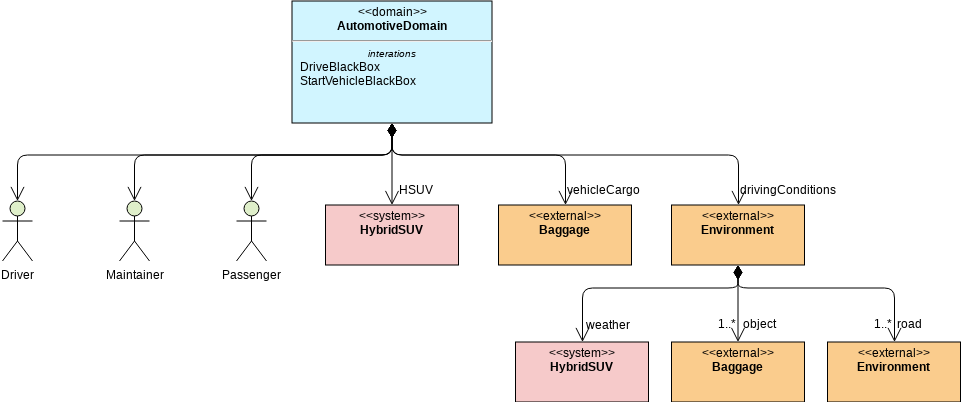
SysML Block Definition Diagram: HSUV Automotive Domain
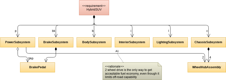
SysML Diagram: HSUV Hybrid SUV System Block Definition
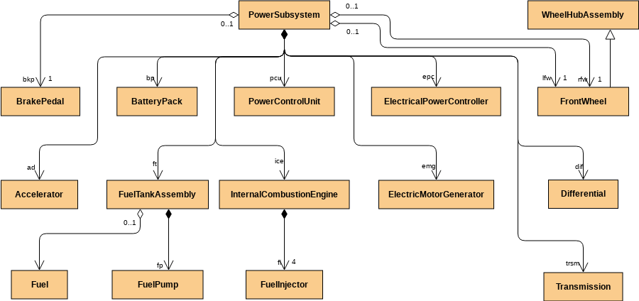
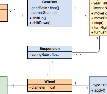
Block Definition Diagram: HSUV Power Subsystem

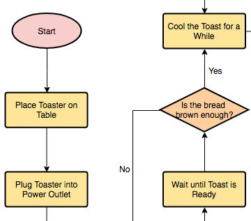
PowerSystem Fuel Flow Block Definition Diagram
Feature Highlights
An easy, powerful online diagram software that lets you create better visuals faster and easier.
-
 Diagram with Ease
Drag and drop shapes to create stunning diagrams in a few clicks. Position shapes neatly with alignment guides.
-
 For Word, Excel, PPT
Embed interactive diagrams in MS applications. Word, PowerPoint, OneNote, and Outlook are supported.
-
 Import Visio Files
Import your Visio files into VP Online. Create and edit diagrams collaboratively, in real-time.
-
 Diagram Export
Export and share diagrams in multiple simple formats such as PNG, JPG, SVG, GIF, and PDF.
-
 Huge Range of Templates
Create fast, professional-looking diagrams with over 2,000 professionally designed templates.
-
 Collaborate Anywhere
Collaborate on your best ideas with the real-time diagram editor. Add comments for discussions.
LEARN MORE ABOUT THE DRAWING FEATURES
Find out more »
More Than Just a SysML Block Definition Diagram Tool

Get Started Now
Create diagrams and charts in a simple and flexible way.
Start Drawing for Free
Comprehensive Diagram Support
-
Technical diagrams: UML, ERD, DFD, PERT, Network diagram, Wiring, PFD, P&ID, and more
-
Business diagrams: ArchiMate, BPMN, SWOT, Value Chain, Value Stream Mapping, Org. Chart, and more
-
Cloud architecture design tool: AWS, Azure, Google Cloud, IBM, Oracle, Alibaba, Tencent
-
Powerful visualization tools: Flowchart, Floor plan, Mind map and Venn diagram tool
-
Process Map Designer with templates like Customer Journey Mapping, Competitor Analysis, Root Cause, etc.
AI-Powered SysML Modeling with Visual Paradigm
Visual Paradigm provides a comprehensive suite for Systems Modeling Language (SysML), recently enhanced with AI-powered generative modeling that automates the creation of complex system diagrams from natural language descriptions [1, 2, 3].
AI-Driven SysML Features
The AI Diagram Generator acts as a “co-pilot” for systems engineering, allowing teams to bypass manual drawing for several key SysML types [4, 5, 6, 7]:
-
Requirement Diagram Generation: Converts technical documents or plain text into structured requirement models. The AI can automatically define requirement IDs, text descriptions, and establish relationships like
<<deriveReqt>>,<<satisfy>>, and<<verify>>. -
Internal Block Diagram (IBD) Automation: Instantly produces detailed IBDs from structural descriptions. It automatically defines internal parts, ports, and connectors, maintaining structural compliance without manual placement.
-
Block Definition Diagram (BDD) Support: AI can generate BDDs for complex systems (e.g., Smart TV or Automotive systems), identifying and adding relevant modules or functions based on user prompts.
-
Traceability & Analysis: AI assistants can analyze models to suggest likely traceability links and perform impact analysis, identifying which components are affected if a specific requirement changes [1, 5, 7, 8, 9, 10, 11, 12, 13].
Core SysML Diagram Suite
Visual Paradigm supports all nine standard SysML diagram types, grouped by their focus [14, 15]:
| Category | Diagram Types | Purpose |
|---|---|---|
| Structural | Block Definition (BDD) | Models system hierarchy and classification |
| Internal Block (IBD) | Models internal structure and connections via ports | |
| Package | Organizes model elements into hierarchies | |
| Parametric | Defines quantitative constraints for performance analysis | |
| Behavioral | Activity | Models system processes and data flows using swimlanes |
| Sequence | Focuses on how system parts interact over time | |
| State Machine | Shows how components change state in response to events | |
| Use Case | Captures high-level functional requirements | |
| Requirements | Requirement | Visualizes textual requirements and their relationships |
Advanced Modeling Capabilities
-
MBSE Integration: Facilitates Model-Based Systems Engineering (MBSE) by integrating requirements, structure, and behavior into a single cohesive model.
-
Flexible Allocation Tables: Provides specialized tables for functional, structural, and requirement allocations, which are more robust than standard UML options.
-
Simulation Support: Parametric diagrams can be used to mathematically constrain blocks, enabling system performance simulations.
-
Collaboration & Sync: Diagrams are fully editable after AI generation and can be synchronized across different views to ensure architectural consistency [17, 19, 25, 26, 27, 28].
Getting Started: Quick Steps to Create Your First BDD
-
Sign Up or Log In: Visit Visual Paradigm Online and create a free account.
-
Select Block Definition Diagram: Navigate to the diagram creation menu and choose “Block Definition Diagram” under SysML templates.
-
Use Drag-and-Drop: Add blocks, properties, operations, and relationships using the intuitive toolbar.
-
Customize Elements: Define block attributes, constraints, and relationships using the property panels.
-
Leverage AI Assistance: Use the AI Diagram Generator to auto-create diagrams from natural language descriptions.
-
Export & Share: Download your diagram in PNG, PDF, SVG, or embed it directly into Microsoft Office applications.
💡 Pro Tip: Start with one of the free automotive domain examples above to understand best practices for structuring complex system hierarchies.
Conclusion
- Create polished BDDs using drag-and-drop simplicity and pre-built automotive domain templates
- Leverage AI to auto-generate requirement diagrams, internal block structures, and traceability links from natural language descriptions
- Navigate the full suite of nine SysML diagram types to model structure, behavior, and requirements cohesively
- Integrate your diagrams into MBSE workflows, Microsoft Office documents, and team collaboration pipelines
Your next great system design starts now.
Launch Visual Paradigm Online and create your first Block Definition Diagram—free
Reference
- Visual Paradigm SysML Diagram Tool Features: Official documentation covering SysML diagram creation capabilities, supported diagram types, and modeling features in Visual Paradigm.
- Visual Paradigm SysML Diagram Tool Features: Comprehensive overview of SysML modeling tools, including Block Definition Diagrams, Internal Block Diagrams, and requirements tracing.
- Comprehensive Review: Visual Paradigm’s AI Diagram Generation Features: Independent review analyzing Visual Paradigm’s AI-powered diagram generation capabilities for SysML and other modeling languages.
- AI Diagram Generation Features by Visual Paradigm: Official feature page detailing how AI assists in generating SysML diagrams from natural language prompts.
- SysML Requirement Diagram: A Guide to AI-Powered Requirements Engineering: Step-by-step guide on using AI to generate and manage SysML requirement diagrams with traceability links.
- AI Diagram Generation Features by Visual Paradigm: Documentation on AI co-pilot functionality for automating SysML diagram creation and model synchronization.
- Visual Paradigm SysML Diagram Tool Features: Detailed feature breakdown of SysML support including BDD, IBD, parametric diagrams, and MBSE workflows.
- YouTube Video: Visual Paradigm SysML Tutorial: Video tutorial demonstrating SysML diagram creation workflows and best practices in Visual Paradigm.
- YouTube Video: Visual Paradigm SysML Tutorial: Practical demonstration of building Block Definition Diagrams and establishing system hierarchies.
- SysML Requirement Diagram: A Guide to AI-Powered Requirements Engineering: Advanced guide covering AI-assisted requirement derivation, satisfaction links, and verification relationships.
- YouTube Video: Visual Paradigm AI Features Demo: Demo showcasing AI diagram generation capabilities for SysML models using natural language input.
- YouTube Video: Visual Paradigm SysML Modeling Guide: Comprehensive walkthrough of SysML modeling techniques including structural and behavioral diagrams.
- YouTube Video: Visual Paradigm SysML Modeling Guide: Tutorial covering advanced SysML features like parametric constraints and allocation tables.
- Visual Paradigm Guide: MBSE and SysML: Official guide explaining Model-Based Systems Engineering principles and SysML implementation strategies.
- PTC Blog: SysML vs UML Comparison: Comparative analysis of SysML and UML, highlighting when to use each modeling language for systems engineering projects.
- Visual Paradigm Guide: SysML Model Element Structure: Documentation on organizing SysML model elements, packages, and hierarchical relationships.
- Beginner’s Guide to SysML Internal Block Diagrams: Entry-level tutorial on creating Internal Block Diagrams with ports, flows, and connectors.
- Visual Paradigm SysML Diagram Tool Features: Feature reference for SysML diagram types, templates, and collaboration tools.
- Visual Paradigm Guide: MBSE and SysML: In-depth resource on integrating SysML models into MBSE workflows for complex system development.
- Visual Paradigm Guide: How to Use Activity Diagrams in SysML: Tutorial on modeling system behaviors and workflows using SysML Activity Diagrams.
- Draw.io Blog: SysML vs UML Differences: Comparative article discussing key distinctions between SysML and UML for system modeling.
- Visual Paradigm Guide: Modeling Scenarios with Sequence Diagrams: Guide to capturing interaction scenarios and message flows using SysML Sequence Diagrams.
- Visual Paradigm Guide: Using State Diagrams to Model Behavior: Tutorial on representing component state transitions and event-driven behavior in SysML.
- SysML Requirement Diagram: A Guide to AI-Powered Requirements Engineering: AI-focused guide for automating requirement modeling and traceability in SysML projects.
- Visual Paradigm Chinese Guide: MBSE and SysML: Chinese-language resource covering MBSE methodologies and SysML implementation in Visual Paradigm.
- Visual Paradigm Guide: MBSE and SysML Integration: Comprehensive guide on aligning SysML models with MBSE practices for end-to-end system development.
- YouTube Video: Visual Paradigm AI Diagram Generation Tutorial: Video demonstration of using AI to generate synchronized, reusable SysML model elements across multiple diagram types.
Ready to start modeling?
Create your first Block Definition Diagram now →
Visual Paradigm Online runs in any browser, requires no installation, and offers a free tier to get started with professional SysML modeling today.